Nonrigid Joints
As a default, all beams connected at a point are assumed to be rigidly coupled to each other. Sometimes, this is not the case in a true structure. One common case is the addition of hinges in a frame to avoid intrinsic stresses caused by for example thermal expansion or tolerance deviations.
To model such joints, you use the Beam End Release node. In that node, you can specify that some degrees of freedom are decoupled at a certain point.
Using Edge Groups
If more than two beams are attached to such a point, the decoupling is however not unique. Consider a case where four beams meet at right angles, and that there is a hinge at the common point as shown in Figure 8-2. To model the hinge, the out-of-plane rotation is selected as a decoupled degree of freedom in the Beam End Release node.
Figure 8-2: Original configuration.
There are several ways in which a hinge at the common connection point can be interpreted. Some examples are shown in Figure 8-3 to Figure 8-5. The default behavior is that all beams are disconnected in terms of rotation, as displayed in Figure 8-3.
Figure 8-3: All beams are free to rotate relative to each other.
Figure 8-4: Beam 1 is free to rotate with respect to the other three beams.
Figure 8-5: Beams 1 and 3 rotate as a common part with respect to beams 2 and 4.
If you want to describe non-default types of connections, you need to add one or more Edge Group subnodes to the 
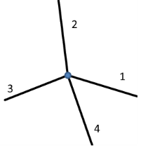
Beam End Release node. If just a single beam is disconnected, as in Figure 8-4, then you need a single edge group in which you select the other three beams (2, 3, and 4).
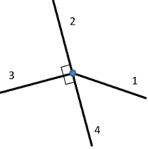
To describe the case in Figure 8-5, you add two edge groups. You then select beams 1 and 3 in the first one, and beams 2 and 4 in the second one.
Generally speaking, a beam assigned to an edge group will not have any degrees of freedom released with respect to other beams in the same group. A beam cannot belong to more than one edge group.
Stress Analysis of a Portal Crane: Application Library path Structural_Mechanics_Module/Beams_and_Shells/portal_crane
Finite Rotations
In a geometrically nonlinear study, there may be finite rotations. In that case, the axis orientations along which degrees of freedoms are released will be updated based on the rotation of the beam itself. For the most common type of connections, this will be the intended behavior.
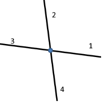
There are, however, some cases when the orientations can become ambiguous. Consider, for example, a 2D case where both the X-translation and the out-of-plane rotation are decoupled where two beams meet. This situation is shown in Figure 8-6. Since the rotation is now different in the two beams, so is the definition of a rotated X direction. Depending on the physical arrangement, the translational sliding motion can follow either of the two connected beams. In the section Edge Defining the Local Direction in the settings for Beam End Release, you can select the edge that controls the rotation of the coordinate system under finite rotations.
Figure 8-6: From left to right: Original configuration, deformed with X interpreted from beam 2, and deformed with X interpreted from beam 1.