Radial Roller Bearing
In this type of bearing, relative rotation between the two components is allowed by inserting rolling elements between them. These bearings typically consist of the inner race, rollers (ball or cylindrical rollers), and the outer race. The inner race is interference fitted on the shaft whereas the outer race is fixed to the casing. A cage is used to keep the rollers well separated.
During the operation, rollers are in contact with the inner and outer race surfaces and roll in between whenever there is a relative motion between these surfaces. Inner and outer surfaces can, in general, be curved in both the directions perpendicular to the normal. Therefore, modeling of roller bearings requires a detailed analysis of how the contact interaction takes places between the inner race and roller, and the roller and outer race. Contact between the rolling element and the races can be of two types, namely, a point contact such as contact between ball and races or a line contact such as contact between the cylindrical roller and races.
Force in Point Contact
Consider two solids having different radii of curvature in two tangential directions which are in point contact when no load is applied. Under the action of the load F, the contact area becomes elliptical. As a convention, let us assign the positive sign for the curvature of a convex surface and negative for a concave surface. The contact profile between the two solids A and B can be expressed in terms of the curvature sum, R, and curvature difference, Rd, as follows:
Indices 1 and 2 represent the local tangent directions. R1 and R2 are the effective radius of curvatures of the contacting surfaces in the local direction given by:
The point of contact under the action of the load expands to an ellipse with semi-major axis, ae, and semi-minor axis, be. The ellipticity parameter is defined as:
This ellipticity parameter can be defined in terms of the curvature difference, Rd, and elliptic integrals of first and second kind as follows:
where ξ and ζ are the elliptic integrals of first and second kind, respectively, defined as:
An approximate formula for the ellipticity and elliptical integrals of first and second kind can be given as:
The contact stiffness for point contact then can be evaluated in terms of the elliptic integrals and ellipticity parameters as follows:
with E' defined as:
The contact force for the point contact is
where δ is the penetration of the surfaces into each other.
Therefore, an equivalent stiffness corresponding to both inner and outer contacts is:
Determination of the contact stiffness requires the radius of curvatures of the contacting surfaces in the tangential directions. For different point contact bearings these are given below.
Deep Groove Ball Bearing
Ball and inner race contact:
Ball and outer race contact:
Angular Contact Ball Bearing
Ball and inner race contact:
Ball and outer race contact:
Self-Aligning Ball Bearing
Ball and inner race contact:
Ball and outer race contact:
Spherical Roller Bearing
roller and inner race contact:
roller and outer race contact:
Force in Line Contact
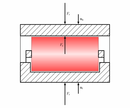
When two cylindrical surfaces with parallel axes come in contact, the contact formed is a line contact. In this case, the force, F, changes the contact area into rectangular. The width of the contact area, b, can be obtained in terms of the applied load, F, equivalent radius of curvature, R, and the effective elastic modulus, E', as:
where L is the length of cylindrical surfaces in contact. The normal displacement is given by:
The derivative of the normal displacement, δ, with respect to the load, F, gives the compliance. The inverse of the compliance is the stiffness of the contacting surfaces.
However, this method requires iterations during the numerical solution to know the contact forces. Based on laboratory testing, Palmgren provided a simple expression to evaluate the contact forces as a function of indentation as:
Therefore, the equivalent stiffness corresponding to the inner and outer contacts is:
Contact Deformation in Point Contact Roller Bearings
Figure 3-2: Front view of roller bearing.
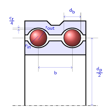
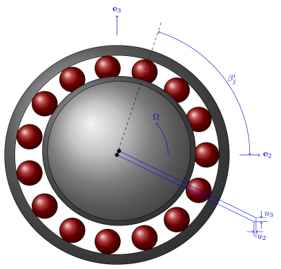
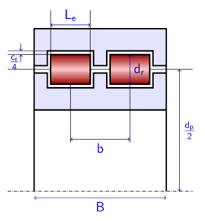
Figure 3-2 shows the front view of a typical roller bearing. Due to the relative motion of the inner race and outer race, some of the rollers get loaded, whereas others get unloaded. This relative motion determines the contact indentation at different rollers. From 
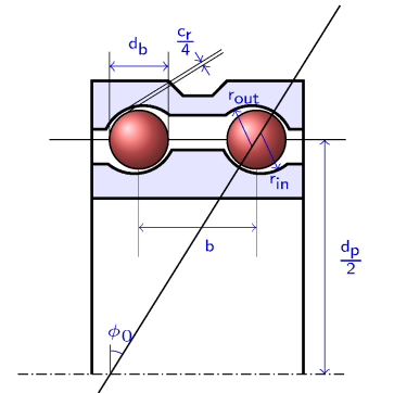
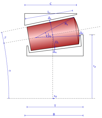
Figure 3-3 the initial distance between the inner and outer race curvature centers is:
along the line
Plus sign is for the second row and minus sign is for the first row of the rollers. In case of a single row bearing φ0 becomes zero. eirj is the radial vector corresponding to the roller i in row j and is defined as:
Figure 3-3: Side view of the roller bearing.
Let the relative center displacement between the inner and outer race be ur, and the relative tilt about local y and z directions be θ2 and θ3 respectively. Then the relative displacement between the inner and outer races at roller i in row j is:
with
for a double row bearing with plus sign for second row and minus sign for the first row, and
for single row bearing. Here, b is the axial distance between the roller centers and dp is the pitch diameter of the bearing. The loaded distance vector between the inner and outer race curvature centers is:
The magnitude of the loaded distance vector is the loaded distance between the curvature centers of the races. The distance between the race surfaces along the common normal in the loaded state then can be calculated as:
Then the indentation at roller i in row j is:
The total contact force on the inner race is then given by:
Only positive values of the contact forces on each roller are taken into account, and negative values are replaced by zero since such rollers are unloaded. For a single row bearing, summation over j is dropped. The contact force on the outer race acts in opposite direction to that on inner race.
The net moment on the rotor from the bearing then can be obtained by
Contact Deformation in Tapered Roller Bearing
In the tapered roller bearing the contact force directions at inner and outer contacts are different. In addition, there is also a contact between the bearing flange and roller. Therefore, it is not possible to directly get the equivalent stiffness of the inner and outer contacts. This requires the determination of the contact forces at inner and outer contacts individually. Geometric details of the tapered roller bearing are shown in the Figure 3-4.
Figure 3-4: Tapered roller bearing geometry
There are three locations at which the roller comes into contact with the inner and outer races, namely radial contact with the outer race, radial contact with the inner race, and axial contact with the inner race. Radial contacts are line contacts, whereas the axial contact between the roller and the inner race is a point contact. In order to determine the contact forces in all these cases, contact deformation in the roller needs to be determined due to the relative motion of the inner and outer races. This can be described conveniently by using a local coordinate system (ξ, η, ζ) in which the ζ direction is along the axis of the roller, ξ is perpendicular to the ζ axis and is in the plane formed by bearing's radial and axial directions. In this coordinate system, the relative in-plane motion (ξ-ζ plane) and tilt about η axis can cause roller deformation.
Figure 3-5: Position vectors of the various points in local coordinate system.
Determination of the roller deformation can be done by first looking at the initial position vectors of the various points which are likely to come into contact, and then determine their current position vector due to the motion of the races. A projection of the difference between the current and initial position vectors gives an estimate to the roller deformation. Using the geometric details given in the Figure 3-4, the position vectors of the various points are as follows:
where ζcs is given by
Introduce the displacement ui and rotation vector θi at the reference point on the inner race, the displacement ue and rotation vector θe at the reference point on the outer race, and the displacement ur and rotation vector 
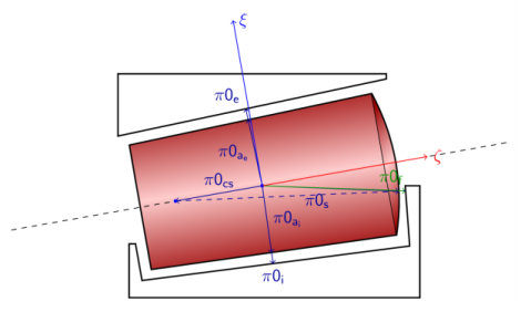
θr at the reference point on the rollers. Then, the displaced position π of the arbitrary point located at π0 from the reference point will be:
where uref and θref are pair (ui, θi) for a point on the inner race, (ue, θe) for a point on the outer race and (ur, θr) for a point on the roller.
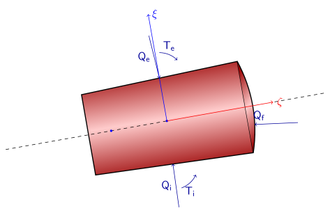
The compression δ at the contact between roller and raceway is found by taking the projection of the current relative position vectors of the nominal contact points on their outside normal vector and removing the initial gap:
The normal vectors in the local coordinate system are given by:
After simplification, the respective indentations are:
In this case, the roller center is chosen as the reference point for both the roller and the races.
The motion of the both the races are determined from the motion of the components they are connected to. For example, the inner race motion can be determined from the rotor and the outer race motion can be determined from the motion of the bearing pedestal. The motion of the roller, however, still remains unknown. It can be determined by considering the load balance of the roller as shown in Figure 3-6.
Figure 3-6: Load balance on the roller
Force balance:
Moment balance:
In the local roller direction, this reduces to:
The contact forces, in terms of roller deformation are:
The corresponding contact moments from line contact are obtained by integrating the local contact forces over the contact line:
where re and ri are the position vectors on the outer and inner contact lines, respectively, with respect to the reference point. dQe and dQi are the infinitesimal forces acting on the infinitesimal length dx on the outer and inner contact lines.
Contact forces and moments then need to be added from each roller to determine the total bearing forces acting on the rotor and bearing pedestal.
Contact Deformation in Cylindrical Roller Bearing
In the cylindrical roller bearing, the forces at inner and outer contact lines are aligned as in the case of the point contact roller bearings. A typical arrangement of a cylindrical roller bearing is shown in Figure 3-7. The initial gap between the outer race and inner race for roller i in row j is given by:
along the line
Here, eirj is the radial vector corresponding to the roller i in row j and is defined as:
Figure 3-7: Geometry of the cylindrical roller bearing.
Let the relative center displacement of the inner race with respect to outer race be ur and the relative tilt about local y and z directions be θ2 and θ3, respectively. Then the relative displacement of the inner with respect to outer races at roller i in row j is:
with
for a double row bearing. Plus sign applies to the second row and minus sign to the first row and
for a single row bearing. b is the axial distance between the roller centers and dp is the pitch diameter of the bearing.
After the loading, the gap vector of the outer race with respect to the inner race is:
Then the indentation at roller i in row j is:
The total contact force on the inner race is then given by:
Only positive values of the contact forces on each roller are taken into account, and negative values are replaced by zero since the roller is unloaded. For a single row bearing, summation over j is dropped. Contact forces on the outer race acts in the opposite direction to those at the inner race.
The net moment on the rotor due to bearing then can be obtained by
Bearing Preload
A bearing preload is usually a sustained axial load that is applied to a bearing to ensure constant contact between the rolling elements and the races. This helps in reducing or eliminating both radial and axial play between the inner and outer races. As a result, the rotational accuracy of the shaft increases with the preload. A proper preload in the bearing can increase the life of the bearing, and also reduce the vibrations and noise that result from the clearance between the races. For some bearings, like the radial roller bearings, a radial preload is applied instead. Preloading of the bearing is mostly used in high precision and high speed applications such as machine tool spindles, electric motor, automotive differentials, and so on.
Axial Preload
An axial preload in the single row bearings can be provided to angular contact ball bearings and tapered roller bearings. For these bearings, the axial preload causes the inner and outer races to move towards each other. Thus, the axial preload directly works as a load on the relative displacement of the inner race and the outer race in such a way that it loads the rollers/balls.
Figure 3-8: Axial preload on a single row angular contact ball bearing.
If the contact direction between the rolling elements and races has a positive projection on the bearing axis, then the preload will push the outer race opposite to the bearing axis and the inner races along the bearing axis. The direction will reverse if the contact direction has a negative projection on the bearing axis. Thus, a weak contribution due to a preload can be expressed as
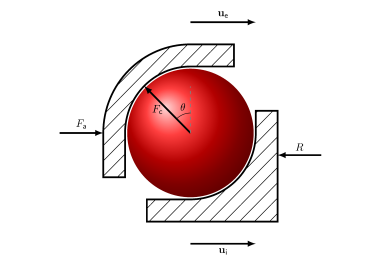
Here, Fa is the axial preload in the bearing, e1 is the bearing axis, ur is the rotor displacement, uf is the foundation displacement and er is the contact direction between the rolling element and the races. Because races of a bearing are connected to the rotor and the foundation, respectively, the displacement of the inner race is equal to the rotor displacement, and the displacement of the outer race is equal to foundation displacement. As you can see, for single row bearings, the preload is also transmitted to the rotor on which the bearing is mounted.
An axial preload in double row bearings can be used with an angular contact ball bearing, a self-aligning ball bearing, a spherical roller bearing and a tapered roller bearing. For double row bearings, the situation more complex. In this case, one of the races in the bearing is split and a preload between the split parts is applied in such a way that they push the rolling elements against the nonsplit race. This loads the rollers in the bearing. Because the races are split, they can move relative to one another.
Figure 3-9: Axial preload in a double row angular contact ball bearing.
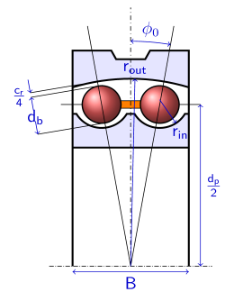
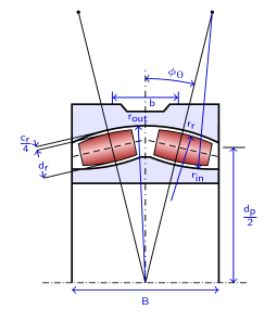
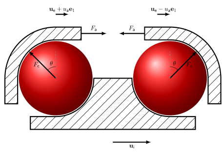
Let us assume that the outer race is split and that the part corresponding to the first row moves by an axial displacement ua along the bearing axis, and that the part corresponding to the second row moves by the same axial displacement but in opposite direction. The weak contribution due to the axial preload, in this case, is
Thus, we see that preload in this case works on the relative axial displacement of the split parts. As a result, a preload in the double row bearings is not transferred to the rotor on which it is mounted. Relative axial displacement between the split parts is determined by the balance of the preload and the roller-race contact reaction forces on each part.
Radial Preload
A radial preload is applied to deep groove ball bearings and cylindrical roller bearings for both single and double rows. Other single row bearings on which a radial preload can be applied are self-aligning ball bearings and spherical roller bearings. This type of preload refers to an interference fit in the bearing.
Figure 3-10: Radial preload in a single row cylindrical roller bearing.
We assume that radial deformation in the bearing is ur due to the preload. Then the weak contribution due to radial preload is
The radial deformation due to a preload is obtained by considering the force balance between the radial preload and roller-race contact reaction force. Due to symmetry, a radial preload is canceled out and there is no net load transferred to the rotor on which bearing is mounted.
Consistency of Geometric Parameters
A roller bearing model requires many geometric parameters as an input. Since, these parameters are specified independently during the modeling, there is a possibility that they are geometrically inconsistent and do not correspond to a physical bearing. A consistency check is implemented to provide a guideline in choosing certain parameters with respect to how other parameters are defined. Let us first define certain terms that are helpful in geometry checks.
Fill angle: A fill angle ψf is the angular space occupied by the rolling elements on a pitch circle.
Figure 3-11: Front view of a ball bearing
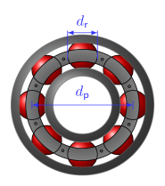
Since each rolling element has a diameter dr and there are N number of them, the arc length occupied on the pitch circle by the rolling elements is Ndr. Furthermore, the pitch circle radius is dp/2. Thus, the angular space occupied by the rollers, that is, the fill angle is
Inner race conformity: Inner race conformity, fin, is the ratio of the inner race radius of curvature to the diameter of the rolling element. It is defined by
Outer race conformity: Outer race conformity, fout, is the ratio of the outer race radius of curvature to the diameter of the rolling element. It is defined by
For a physical bearing, the fill angle cannot be larger than 2π radians. This gives a constraint on the diameter of the roller in relation to the pitch diameter as
Usually the fill angle is much smaller than 2π due to the space occupied by the cage.
For point contact bearings, another constraint comes from the fact that the rolling elements have to fit between the inner race and the grooves of the outer race. As a result, the race radius of curvatures should be larger than the radius of the rolling elements. This means that the race conformity should be larger than 0.5 for both races.
For a tapered roller bearing another geometric constraint is that the flange contact angle, μ0, should be less than the roller cap angle, λ.
If these conditions are violated for any bearing, an error message is thrown with relevant information to identify the parameter causing the problem.