|
 ,
, ,
, .
.


|
1
|
|
2
|
|
3
|
Click Add.
|
|
4
|
Click
|
|
5
|
In the Select Study tree, select Preset Studies for Selected Physics Interfaces>Boundary Mode Analysis.
|
|
6
|
Click
|
|
1
|
|
2
|
|
1
|
|
2
|
|
3
|
|
4
|
|
5
|
|
6
|
|
1
|
|
2
|
|
3
|
|
4
|
|
5
|
|
6
|
|
7
|
|
1
|
|
2
|
|
3
|
|
4
|
|
1
|
|
1
|
In the Model Builder window, expand the Component 1 (comp1)>Definitions>View 1 node, then click Camera.
|
|
2
|
|
3
|
|
4
|
|
5
|
|
6
|
Click
|
|
7
|
|
1
|
In the Model Builder window, under Component 1 (comp1) right-click Materials and choose Blank Material.
|
|
2
|
|
3
|
|
1
|
|
2
|
|
4
|
|
1
|
In the Model Builder window, under Component 1 (comp1) click Electromagnetic Waves, Beam Envelopes (ewbe).
|
|
2
|
In the Settings window for Electromagnetic Waves, Beam Envelopes, type Electromagnetic Waves, Beam Envelopes, Unidirectional in the Label text field.
|
|
3
|
|
4
|
|
1
|
|
3
|
|
4
|
|
1
|
|
3
|
|
4
|
|
1
|
|
2
|
Locate the Electromagnetic Waves, Beam Envelopes, Unidirectional (ewbe) section. In the NT text field, type 20. This will make the triangular mesh on the input boundary resolve the modes.
|
|
3
|
In the NL text field, type 20. This will create a swept mesh with twenty elements along the waveguide. This will be sufficient to resolve the mode-coupling that will occur.
|
|
4
|
|
1
|
|
2
|
|
3
|
|
1
|
|
2
|
|
3
|
|
4
|
|
5
|
|
6
|
|
1
|
|
2
|
In the Settings window for 3D Plot Group, type Electric Field, Unidirectional in the Label text field.
|
|
1
|
|
2
|
In the Settings window for Surface, click Replace Expression in the upper-right corner of the Expression section. From the menu, choose Component 1 (comp1)>Electromagnetic Waves, Beam Envelopes, Unidirectional>Boundary mode analysis>Boundary mode electric field - V/m>ewbe.tEbm1z - Boundary mode electric field, z-component.
|
|
3
|
|
4
|
|
5
|
Click OK.
|
|
1
|
|
2
|
|
3
|
|
4
|
|
5
|
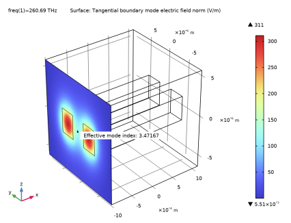
From the Effective mode index list, choose 3.4714, which should be the third largest effective index.
|
|
6
|
|
1
|
|
2
|
|
3
|
|
1
|
|
2
|
|
3
|
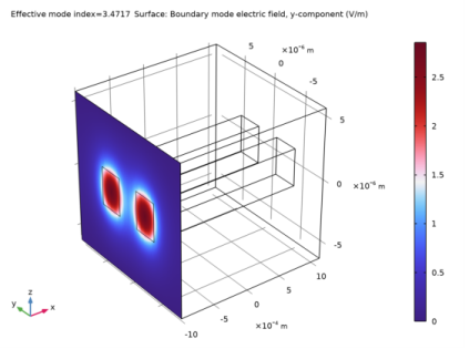
From the Effective mode index list, choose 3.4717, which should be the second largest effective index.
|
|
4
|
|
5
|
|
6
|
|
1
|
|
2
|
In the Settings window for Global Evaluation, click Replace Expression in the upper-right corner of the Expressions section. From the menu, choose Component 1 (comp1)>Electromagnetic Waves, Beam Envelopes, Unidirectional>Ports>Propagation constants>ewbe.beta_1 - Propagation constant - rad/m.
|
|
3
|
Click
|
|
1
|
Go to the Table window.
|
|
2
|
|
3
|
|
1
|
|
2
|
|
3
|
|
4
|
In the Search for modes around text field, type 3.4716717443092047, by selecting the value in your text editor and then copying and pasting it here. This should be the largest effective index. The last figures could be different from what is written here.
|
|
1
|
|
2
|
|
3
|
In the Search for modes around text field, type 3.4714219480792172, by selecting the value in your text editor and then copying and pasting it here. This should be the third largest effective index. The last figures could be different from what is written here.
|
|
4
|
|
1
|
In the Model Builder window, under Study, Unidirectional, Ctrl-click to select Step 1: Boundary Mode Analysis and Step 3: Boundary Mode Analysis 1.
|
|
2
|
Right-click and choose Duplicate.
|
|
1
|
|
2
|
|
1
|
|
2
|
|
3
|
|
1
|
|
2
|
|
3
|
|
4
|
Finally, move Step2: Frequency Domain to be the last study step, either by three times right-clicking it and choosing Move Down or by simply dragging it and dropping it at the last position in the list.
|
|
5
|
|
1
|
In the Model Builder window, under Results>Electric Field, Unidirectional right-click Surface 1 and choose Delete.
|
|
1
|
|
2
|
Click Yes to confirm.
|
|
1
|
|
2
|
|
3
|
|
4
|
|
5
|
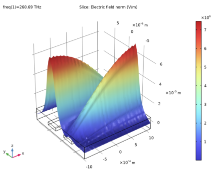
Click to expand the Quality section. From the Smoothing list, choose Everywhere. This makes the deformation plot smooth across the core-cladding interfaces.
|
|
1
|
|
2
|
|
3
|
|
4
|
|
5
|
|
6
|
|
1
|
In the Model Builder window, under Component 1 (comp1)>Electromagnetic Waves, Beam Envelopes, Unidirectional (ewbe) click Port 2.
|
|
2
|
|
3
|
|
1
|
|
1
|
In the Model Builder window, under Component 1 (comp1) right-click Electromagnetic Waves, Beam Envelopes, Unidirectional (ewbe) and choose Copy.
|
|
1
|
In the Model Builder window, right-click Component 1 (comp1) and choose Paste Electromagnetic Waves, Beam Envelopes.
|
|
2
|
|
3
|
In the Settings window for Electromagnetic Waves, Beam Envelopes, type Electromagnetic Waves, Beam Envelopes, Bidirectional in the Label text field.
|
|
4
|
|
5
|
|
6
|
|
1
|
|
2
|
|
3
|
In the table, clear the Use check box for Electromagnetic Waves, Beam Envelopes, Bidirectional (ewbe2).
|
|
1
|
|
2
|
|
3
|
Locate the Physics-Controlled Mesh section. In the table, clear the Use check box for Electromagnetic Waves, Beam Envelopes, Unidirectional (ewbe).
|
|
4
|
Locate the Electromagnetic Waves, Beam Envelopes, Bidirectional (ewbe2) section. In the NL text field, type 5.
|
|
5
|
|
1
|
|
2
|
|
3
|
|
4
|
|
5
|
|
1
|
|
2
|
|
1
|
In the Model Builder window, under Study, Unidirectional, Ctrl-click to select Step 1: Boundary Mode Analysis, Step 2: Boundary Mode Analysis 1, Step 3: Boundary Mode Analysis 2, Step 4: Boundary Mode Analysis 3, and Step 5: Frequency Domain.
|
|
2
|
Right-click and choose Copy.
|
|
1
|
|
2
|
In the Settings window for Boundary Mode Analysis, locate the Physics and Variables Selection section.
|
|
3
|
In the table, clear the Solve for check box for Electromagnetic Waves, Beam Envelopes, Unidirectional (ewbe).
|
|
4
|
|
1
|
|
2
|
In the Settings window for Boundary Mode Analysis, locate the Physics and Variables Selection section.
|
|
3
|
In the table, clear the Solve for check box for Electromagnetic Waves, Beam Envelopes, Unidirectional (ewbe).
|
|
4
|
|
1
|
|
2
|
In the Settings window for Boundary Mode Analysis, locate the Physics and Variables Selection section.
|
|
3
|
In the table, clear the Solve for check box for Electromagnetic Waves, Beam Envelopes, Unidirectional (ewbe).
|
|
4
|
|
1
|
|
2
|
In the Settings window for Boundary Mode Analysis, locate the Physics and Variables Selection section.
|
|
3
|
In the table, clear the Solve for check box for Electromagnetic Waves, Beam Envelopes, Unidirectional (ewbe).
|
|
4
|
|
1
|
|
2
|
|
3
|
In the table, clear the Solve for check box for Electromagnetic Waves, Beam Envelopes, Unidirectional (ewbe).
|
|
4
|
|
5
|
|
1
|
|
2
|
In the Settings window for 3D Plot Group, type Electric Field, Bidirectional in the Label text field.
|
|
3
|
|
1
|
|
2
|
|
3
|
|
1
|
|
2
|
|
3
|
|
4
|
|
1
|
|
2
|
In the Settings window for 3D Plot Group, type Electric Field Amplitude, Bidirectional in the Label text field.
|
|
3
|
|
1
|
|
2
|
|
3
|
|
4
|
|
5
|
|
6
|
|
7
|
|
8
|
|
1
|
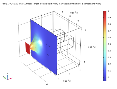
In the Model Builder window, under Component 1 (comp1) right-click Definitions and choose Variables, to define the target field in the cladding and in the right waveguide core.
|
|
2
|
|
3
|
|
5
|
Locate the Variables section. In the table, enter the following settings:
|
|
1
|
|
2
|
|
3
|
|
5
|
Locate the Variables section. In the table, enter the following settings:
|
|
1
|
In the Definitions toolbar, click
|
|
2
|
|
3
|
|
1
|
In the Model Builder window, right-click Component 1 (comp1) and choose Paste Electromagnetic Waves, Beam Envelopes.
|
|
2
|
|
3
|
In the Settings window for Electromagnetic Waves, Beam Envelopes, type Electromagnetic Waves, Beam Envelopes, Bidirectional, Mode Expansion in the Label text field.
|
|
1
|
In the Model Builder window, under Component 1 (comp1) right-click Definitions and choose Variables, to define expressions for the excited port input powers and mode phases.
|
|
2
|
|
1
|
In the Model Builder window, expand the Electromagnetic Waves, Beam Envelopes, Bidirectional, Mode Expansion (ewbe3) node, then click Port 1.
|
|
2
|
|
3
|
|
4
|
|
1
|
|
2
|
|
3
|
|
4
|
|
1
|
|
2
|
|
3
|
|
4
|
|
5
|
|
1
|
In the Model Builder window, under Study, Bidirectional, Ctrl-click to select Step 1: Boundary Mode Analysis, Step 2: Boundary Mode Analysis 1, Step 3: Boundary Mode Analysis 2, Step 4: Boundary Mode Analysis 3, and Step 5: Frequency Domain.
|
|
2
|
Right-click and choose Copy.
|
|
1
|
In the Model Builder window, right-click Study, Bidirectional, Mode Expansion and choose Paste Multiple Items.
|
|
2
|
In the Settings window for Boundary Mode Analysis, locate the Physics and Variables Selection section.
|
|
3
|
In the table, clear the Solve for check box for Electromagnetic Waves, Beam Envelopes, Bidirectional (ewbe2).
|
|
1
|
|
2
|
In the Settings window for Boundary Mode Analysis, locate the Physics and Variables Selection section.
|
|
3
|
In the table, clear the Solve for check box for Electromagnetic Waves, Beam Envelopes, Bidirectional (ewbe2).
|
|
1
|
|
2
|
In the Settings window for Boundary Mode Analysis, locate the Physics and Variables Selection section.
|
|
3
|
In the table, clear the Solve for check box for Electromagnetic Waves, Beam Envelopes, Bidirectional (ewbe2).
|
|
1
|
|
2
|
In the Settings window for Boundary Mode Analysis, locate the Physics and Variables Selection section.
|
|
3
|
In the table, clear the Solve for check box for Electromagnetic Waves, Beam Envelopes, Bidirectional (ewbe2).
|
|
1
|
|
2
|
|
3
|
In the table, clear the Solve for check box for Electromagnetic Waves, Beam Envelopes, Bidirectional (ewbe2).
|
|
4
|
|
1
|
In the Settings window for 3D Plot Group, type Electric Field, Bidirectional, Mode Expansion in the Label text field.
|
|
1
|
In the Model Builder window, expand the Electric Field, Bidirectional, Mode Expansion node, then click Electric Field.
|
|
2
|
|
3
|
|
4
|
|
5
|
|
1
|
|
2
|
|
3
|
|
4
|
|
1
|
|
2
|
In the Settings window for 3D Plot Group, type Electric Field, Difference Between Actual and Target in the Label text field.
|
|
3
|
Locate the Data section. From the Dataset list, choose Study, Bidirectional, Mode Expansion/Solution 11 (sol11).
|
|
1
|
|
2
|
|
3
|
|
1
|
|
2
|
|
3
|
|
4
|
Locate the Scale section.
|
|
5
|
|
1
|
In the Model Builder window, right-click Electric Field, Difference Between Actual and Target and choose Surface.
|
|
2
|
|
3
|
|
4
|
|
1
|
|
1
|
|
2
|
|
3
|
|
4
|
|
1
|
|
1
|
|
3
|
|
1
|
|
1
|
|
2
|
