
|
|
|


|
8·108 Pa
|
||
|
8·107 Pa
|
||

|
1
|
|
2
|
In the Application Libraries window, select Subsurface Flow Module>Flow and Solid Deformation>terzaghi_compaction in the tree.
|
|
3
|
Click
|
|
1
|
|
2
|
|
3
|
|
4
|
Find the Physics interfaces in study subsection. In the table, clear the Solve check box for Study 1.
|
|
5
|
|
6
|
|
1
|
|
2
|
|
3
|
|
4
|
Find the Multiphysics couplings in study subsection. In the table, clear the Solve check box for Study 1.
|
|
5
|
|
6
|
|
1
|
|
1
|
|
1
|
|
2
|
|
3
|
|
1
|
|
2
|
|
1
|
In the Model Builder window, expand the Component 1 (comp1)>Materials node, then click Porous Material 1 (pmat1).
|
|
2
|
|
1
|
|
2
|
|
1
|
In the Model Builder window, expand the Component 1 (comp1)>Definitions node, then click Variables 3.
|
|
2
|
|
1
|
|
2
|
|
3
|
|
4
|
|
5
|
|
1
|
|
2
|
|
3
|
Click
|
|
4
|
|
5
|
|
6
|
Click Replace.
|
|
7
|
|
8
|
Click
|
|
9
|
|
10
|
|
11
|
|
12
|
Click Add.
|
|
13
|
|
1
|
|
2
|
In the Settings window for 2D Plot Group, type Hydraulic Head, Poroelasticity in the Label text field.
|
|
3
|
|
1
|
|
2
|
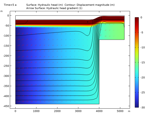
In the Settings window for Surface, click Replace Expression in the upper-right corner of the Expression section. From the menu, choose Component 1 (comp1)>Darcy’s Law>Velocity and pressure>dl.H - Hydraulic head - m.
|
|
1
|
|
2
|
In the Settings window for Contour, click Replace Expression in the upper-right corner of the Expression section. From the menu, choose Component 1 (comp1)>Solid Mechanics>Displacement>solid.disp - Displacement magnitude - m.
|
|
3
|
|
4
|
|
5
|
|
6
|
|
7
|
|
8
|
|
1
|
|
2
|
|
3
|
|
4
|
|
5
|
|
6
|
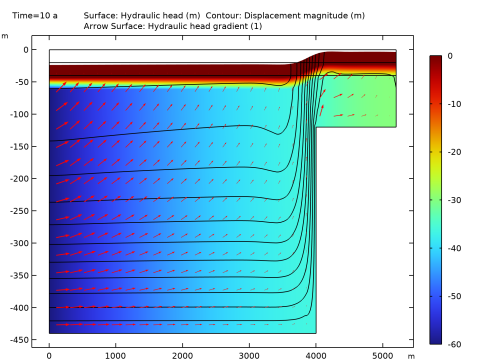
Locate the Arrow Positioning section. Find the X grid points subsection. In the Points text field, type 25.
|
|
1
|
|
2
|
|
3
|
|
4
|
|
1
|
|
2
|
|
3
|
|
1
|
|
2
|
|
3
|
|
4
|
|
5
|
|
6
|
|
7
|
|
8
|
|
1
|
|
2
|
|
1
|
|
2
|
|
3
|
|
1
|
|
2
|
|
3
|
|
1
|
|
2
|
|
3
|
|
4
|
|
5
|
|
6
|
|
7
|
Locate the Coloring and Style section. Find the Point style subsection. From the Color list, choose White.
|
|
8
|
|
1
|
|
2
|
In the Settings window for 2D Plot Group, type Solid-to-Fluid Coupling Term in the Label text field.
|
|
3
|
|
4
|
|
1
|
|
2
|
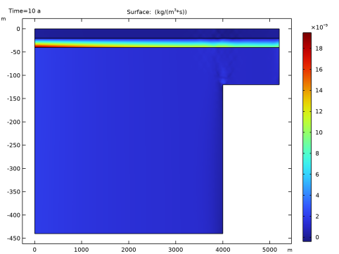
In the Settings window for Surface, click Replace Expression in the upper-right corner of the Expression section. From the menu, choose Component 1 (comp1)>Definitions>Variables>Q_biot - kg/(m³·s).
|
|
3
|
|
1
|
|
2
|
|
3
|
|
4
|
|
5
|
|
1
|
|
2
|
|
3
|
|
4
|
|
5
|
|
1
|
|
2
|
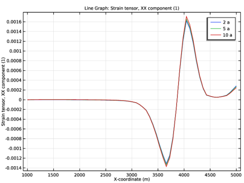
In the Settings window for Line Graph, click Replace Expression in the upper-right corner of the y-Axis Data section. From the menu, choose Component 1 (comp1)>Solid Mechanics>Strain>Strain tensor (material and geometry frames)>solid.eXX - Strain tensor, XX component.
|
|
3
|
|
4
|
Click Replace Expression in the upper-right corner of the x-Axis Data section. From the menu, choose Component 1 (comp1)>Geometry>Coordinate (material and geometry frames)>X - X-coordinate.
|
|
5
|
|
6
|
|
1
|
|
2
|
|
3
|
In the Settings window for 2D Plot Group, type Hydraulic Head, Poroelasticity, Array in the Label text field.
|
|
4
|
|
5
|
|
6
|
|
7
|
|
1
|
|
2
|
|
3
|
|
4
|
|
1
|
|
2
|
|
3
|
|
4
|
|
1
|
|
2
|
|
3
|
|
4
|
|
1
|
In the Model Builder window, under Results>Hydraulic Head, Poroelasticity, Array, Ctrl-click to select Surface 1, Contour 1, and Arrow Surface 1.
|
|
2
|
Right-click and choose Duplicate.
|
|
1
|
|
2
|
|
3
|
|
4
|
Click to expand the Inherit Style section. From the Plot list, choose Surface 1. This step is done to make sure that only one legend is used for the different plots within the array.
|
|
5
|
|
1
|
|
2
|
|
3
|
|
4
|
|
5
|
|
1
|
|
2
|
|
3
|
|
4
|
|
5
|
|
6
|
|
1
|
In the Model Builder window, under Results>Hydraulic Head, Poroelasticity, Array, Ctrl-click to select Surface 2, Contour 2, and Arrow Surface 2.
|
|
2
|
Right-click and choose Duplicate.
|
|
1
|
|
2
|
|
3
|
|
4
|
|
1
|
|
2
|
|
3
|
|
4
|
|
5
|
|
1
|
|
2
|
|
3
|
|
4
|
|
5
|
|
1
|
In the Model Builder window, under Results>Hydraulic Head, Poroelasticity, Array, Ctrl-click to select Surface 3, Contour 3, and Arrow Surface 3.
|
|
2
|
Right-click and choose Duplicate.
|
|
1
|
|
2
|
|
3
|
|
1
|
|
2
|
|
3
|
|
4
|
|
1
|
|
2
|
|
3
|
|
4
|
|
1
|
|
2
|
|
3
|
|
5
|
|
6
|
|
7
|
|
1
|
|
2
|
|
3
|
|
4
|
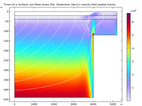
In the Title text area, type Surface: Hydraulic head (m) Contour: Displacement magnitude (m) Arrow Surface: Hydraulic head gradient (1).
|
|
5
|
|
6
|
|
7
|