
|
|
1
|
|
2
|
In the Select Physics tree, select Fluid Flow>Single-Phase Flow>Turbulent Flow>Turbulent Flow, Algebraic yPlus (spf).
|
|
3
|
Click Add.
|
|
4
|
|
5
|
In the Velocity field components table, enter the following settings:
|
|
6
|
|
7
|
Click Add.
|
|
8
|
|
9
|
Right-click and choose Remove.
|
|
10
|
Click
|
|
11
|
In the Select Study tree, select Preset Studies for Selected Physics Interfaces>Turbulent Flow, Algebraic yPlus>Time Dependent with Initialization.
|
|
12
|
Click
|
|
1
|
|
2
|
|
1
|
|
2
|
|
3
|
|
1
|
|
2
|
|
3
|
|
4
|
|
5
|
|
6
|
|
1
|
|
2
|
|
3
|
|
4
|
|
5
|
|
1
|
|
2
|
|
3
|
|
4
|
|
5
|
|
6
|
|
1
|
|
2
|
Click in the Graphics window and then press Ctrl+A to select all objects.
|
|
3
|
|
4
|
|
1
|
|
2
|
On the object uni1, select Point 6 only.
|
|
3
|
|
4
|
|
1
|
|
2
|
On the object fil1, select Point 3 only.
|
|
3
|
|
4
|
|
1
|
|
2
|
|
3
|
|
4
|
|
1
|
|
2
|
On the object sq1, select Point 4 only.
|
|
3
|
|
4
|
|
1
|
|
2
|
|
3
|
|
4
|
|
5
|
|
1
|
|
2
|
|
3
|
|
4
|
|
5
|
|
6
|
|
1
|
|
2
|
On the object c1, select Domain 1 only.
|
|
3
|
On the object fil3, select Domain 1 only.
|
|
4
|
|
5
|
Find the Vertices defining line segments subsection. Click to select the
|
|
6
|
|
7
|
On the object c1, select Boundary 1 only.
|
|
8
|
On the object fil3, select Boundary 5 only.
|
|
1
|
|
2
|
Select the object pard1(1) only.
|
|
3
|
|
4
|
|
1
|
|
2
|
|
3
|
|
4
|
|
1
|
|
2
|
|
3
|
|
4
|
|
1
|
|
2
|
|
3
|
|
1
|
|
2
|
|
3
|
|
4
|
|
5
|
In the tree, select Built-in>Nylon.
|
|
6
|
|
7
|
|
8
|
|
9
|
|
1
|
|
3
|
|
4
|
|
1
|
|
3
|
|
4
|
|
5
|
|
6
|
In the Settings window for Materials, in the Graphics window toolbar, click
|
|
1
|
|
1
|
In the Definitions toolbar, click
|
|
1
|
|
2
|
|
3
|
|
4
|
|
5
|
|
6
|
Find the Intervals subsection. In the table, enter the following settings:
|
|
7
|
|
8
|
|
1
|
|
2
|
|
3
|
|
4
|
|
5
|
|
6
|
Find the Intervals subsection. In the table, enter the following settings:
|
|
7
|
|
8
|
|
1
|
|
2
|
|
3
|
|
4
|
|
5
|
|
1
|
|
2
|
|
3
|
|
1
|
|
2
|
|
3
|
|
5
|
|
1
|
|
2
|
|
1
|
|
3
|
|
4
|
|
1
|
|
3
|
|
4
|
From the list, choose Pressure.
|
|
5
|
|
6
|
|
1
|
|
3
|
|
4
|
|
5
|
|
1
|
|
1
|
|
1
|
|
3
|
|
4
|
|
5
|
From the list, choose Diagonal.
|
|
6
|
|
1
|
|
2
|
|
3
|
|
1
|
|
3
|
|
4
|
|
1
|
|
2
|
In the Settings window for Contact, click to expand the Contact Surface Offset and Adjustment section.
|
|
3
|
In the doffset,d text field, type offset to prevent the part from getting physically in contact. This way, the topology of the moving mesh domain is kept.
|
|
1
|
In the Model Builder window, under Component 1 (comp1)>Multiphysics click Fluid-Structure Interaction 1 (fsi1).
|
|
2
|
|
3
|
|
1
|
|
2
|
|
3
|
|
4
|
|
1
|
|
2
|
|
3
|
|
4
|
|
1
|
|
2
|
|
3
|
In the Model Builder window, expand the Study 1>Solver Configurations>Solution 1 (sol1)>Dependent Variables 2 node, then click Pressure (comp1.p).
|
|
4
|
|
5
|
|
6
|
|
7
|
In the Model Builder window, under Study 1>Solver Configurations>Solution 1 (sol1)>Dependent Variables 2 click Spatial mesh displacement (comp1.spatial.disp).
|
|
8
|
|
9
|
|
10
|
In the Model Builder window, under Study 1>Solver Configurations>Solution 1 (sol1)>Dependent Variables 2 click Velocity field (spatial frame) (comp1.u_fluid).
|
|
11
|
|
12
|
|
13
|
|
14
|
In the Model Builder window, under Study 1>Solver Configurations>Solution 1 (sol1)>Dependent Variables 2 click Displacement field (comp1.u_solid).
|
|
15
|
|
16
|
|
17
|
In the Model Builder window, under Study 1>Solver Configurations>Solution 1 (sol1) click Time-Dependent Solver 1.
|
|
18
|
|
19
|
|
20
|
Right-click Study 1>Solver Configurations>Solution 1 (sol1)>Time-Dependent Solver 1 and choose Automatic Remeshing.
|
|
21
|
|
22
|
|
23
|
|
24
|
Click
|
|
1
|
|
2
|
|
3
|
|
4
|
|
5
|
|
1
|
|
2
|
|
3
|
|
4
|
|
5
|
|
6
|
Click OK.
|
|
1
|
|
2
|
|
3
|
|
4
|
|
1
|
|
2
|
|
3
|
|
4
|
|
1
|
|
2
|
|
4
|
|
5
|
|
6
|
|
1
|
|
2
|
|
4
|
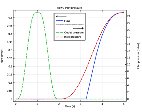
Locate the Coloring and Style section. Find the Line style subsection. From the Line list, choose Dashed.
|
|
5
|
|
1
|
|
2
|
|
4
|
Locate the Coloring and Style section. Find the Line style subsection. From the Line list, choose Dashed.
|
|
5
|
|
6
|
|
1
|
|
2
|
|
3
|
|
4
|
|
5
|
|
6
|
|
7
|
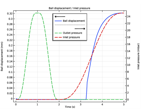
Select the Secondary y-axis label check box. In the associated text field, type Inlet pressure (mbar).
|
|
8
|
|
9
|
|
10
|
|
1
|
|
2
|
|
3
|
|
1
|
|
3
|
|
4
|
|
5
|
|
6
|
|
7
|
|
8
|
|
1
|
|
2
|
Right-click and choose Copy.
|
|
1
|
|
2
|
|
3
|
|
4
|
|
5
|
Select the Secondary y-axis label check box. In the associated text field, type Inlet pressure (mbar).
|
|
6
|
|
7
|
|
8
|
|
1
|
|
2
|
|
3
|
|
4
|
|
1
|
|
2
|
|
4
|
|
5
|
|
6
|
|
7
|
|
8
|
|
1
|
|
2
|
|
3
|
|
4
|
|
5
|
|
6
|
|
1
|
|
3
|
|
4
|
|
5
|
|
6
|
|
7
|
|
8
|
|
9
|
|
1
|
|
2
|
Right-click and choose Copy.
|
|
1
|
|
2
|
|
4
|
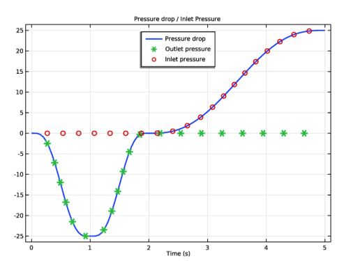
Locate the Coloring and Style section. Find the Line style subsection. From the Line list, choose None.
|
|
5
|
|
6
|
|
7
|
|
1
|
|
2
|
|
3
|
|
4
|
|
5
|
|
6
|
|
7
|
|
1
|
|
2
|
|
3
|
|
4
|
|
5
|
|
6
|
|
1
|
|
2
|
|
3
|
|
4
|
|
5
|
Locate the Coloring and Style section. Find the Point style subsection. From the Type list, choose Arrow.
|