PDF

Comparison of Campbell Plots Using Different Rotor Interfaces
Introduction
When modeling rotor systems, different physics interfaces can be used depending on the required level of detail and the type of system. The modeling steps as well as the result interpretations may differ for the different interfaces. In this example, an eigenfrequency analysis of a rotor system is performed using different physics interfaces available for rotor modeling in COMSOL Multiphysics; namely the Solid Rotor interface, the Solid Rotor, Fixed Frame interface, and the Beam Rotor interface. The analyzed rotor consists of a stepped shaft supported by bearings at three different locations. The Campbell diagrams as computed with the different interfaces are compared to each other. The model also helps in understanding the modeling steps involved in each interface.
Model Definition
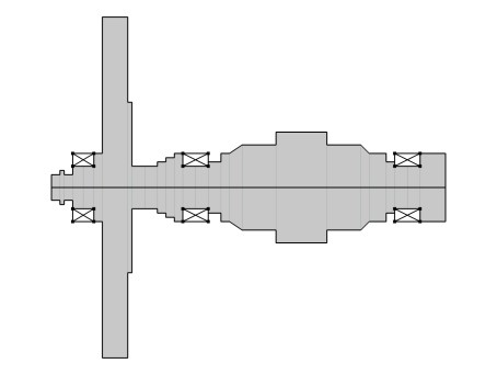
The model consists of a stepped rotor supported on three bearings. The overall rotor configuration is shown in Figure 1.
Figure 1: Rotor geometry.
The locations of different rotor stations along the axial direction are given in Table 1.
Diameters of the rotor between different stations are given in Table 2.
The rotor is made of structural steel. It is tapered between stations 18 and 19 as well as between stations 22 and 23. Three identical bearings hold the rotor in place. The first bearing spans from stations 4 to 6, the second bearing spans from stations 14 to 16 and the third bearing spans from stations 25 to 27. All bearings have an isotropic stiffness of 1e8 N/m.
Stress Stiffening and Gyroscopic Moment
The rotor spin produces stresses even in the absence of external loads. Therefore, the effective stiffness of a stationary rotor differs from a spinning rotor due to the so-called stress stiffening effect. This difference in the stiffness is also referred to as geometric stiffness. When performing an eigenfrequency analysis by itself using the Solid Rotor interface, the geometric stiffness effect will be absent. To capture the geometric stiffness, a prestressed eigenfrequency analysis must be performed. This analysis consists of a study sequence including a stationary and an eigenfrequency analysis. The stationary study captures the stress state in the rotor due to it spinning. The stationary solution is then used as a linearization point in the eigenfrequency study to account for the stress stiffening effect. Note that the eigenfrequency study should use a geometrically nonlinear formulation, as otherwise, it would be equivalent to considering an unstressed state of the rotor as a linearization point and hence there is no stress stiffening effect. If you add the special study type Eigenfrequency, Prestressed, these settings are automatically taken care of. For a manually added study steps you need to change the settings manually.
In a Beam Rotor interface, only the rotor axis is explicitly considered as part of the rotor geometry. Therefore, the stress state due to rotor spin cannot be obtained in a beam rotor model. However, the gyroscopic moment in the beam rotor allows for an equivalent consideration of the geometric stiffness. Since gyroscopic moments are always present in the beam rotor interface, a prestressed analysis is not required.
Coordinate Frames and Result Interpretations
The Solid Rotor interface formulates the problem in a co-rotating frame. Thus, all results, including eigenfrequencies, should be interpreted with respected to an observer sitting in the co-rotating frame. As a result, the eigenfrequencies as observed from a space-fixed frame require some adjustment with respect to the corresponding eigenfrequencies in the co-rotating frame. The whirling mode frequencies in co-rotating frame should be shifted by the angular speed of the rotor in either direction depending on the relative direction of the whirl with respect to the spin direction of the rotor. If the whirl and spin directions are equal, then the rotor speed is added in the co-rotating frame frequency, otherwise the rotor speed is subtracted to get the effective frequency in a space-fixed frame. Axial and torsional vibration frequencies usually remain same in both co-rotating and space fixed frames, thus, do not require any adjustment. This transformation is done internally in the Solid Rotor interface, and corresponding variables in a space-fixed frame can be conveniently evaluated in post-processing. By default, the Solid Rotor interface generates two Campbell diagrams, one in a co-rotating frame and a second in a fixed frame. Critical speeds of the rotor can be obtained using both Campbell diagrams. However, different procedures are required. You can follow the standard procedure of looking at the intersection points of the ω=Ω curve with the eigenfrequency curves to determine the critical speed from a Campbell diagram in a fixed frame. For a Campbell diagram in a co-rotating frame, forward whirl critical speeds are the intersection of eigenfrequency curves with the x-axis (ω=0) and the backward whirl critical speeds are the intersection of eigenfrequency curves with the ω=2Ω curve.
The Beam Rotor and Solid Rotor, Fixed Frame interfaces formulate the problem in a space-fixed frame. The results from these interfaces must therefore be interpreted as observed from a space-fixed frame. Eigenfrequencies do not require any transformation in these interfaces. The default Campbell diagram from these interfaces should be compared with the space-fixed Campbell diagram in the Solid Rotor interface.
Results and Discussion
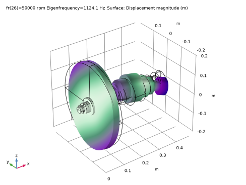
The sixth eigenmode of the rotor is shown in Figure 2 and a corresponding whirl plot is shown in Figure 3.
Figure 2: Sixth eigenmode computed using the Solid Rotor interface.
Figure 3: Whirl plot for the sixth mode computed using the Solid Rotor interface.
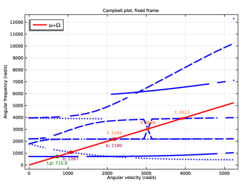
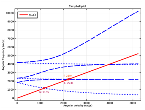
Figure 4 below shows the Campbell diagram obtained from the Solid Rotor interface in a space-fixed frame.
Figure 4: Campbell diagram computed using the Solid Rotor interface.
The eighth eigenmode in the Solid Rotor, Fixed Frame interface is shown in Figure 5.
Figure 5: The eighth mode computed with the Solid Rotor, Fixed Frame interface.
The corresponding whirl plot is shown in Figure 6.
Figure 6: Whirl plot of the eighth mode computed with the Solid Rotor, Fixed Frame interface.
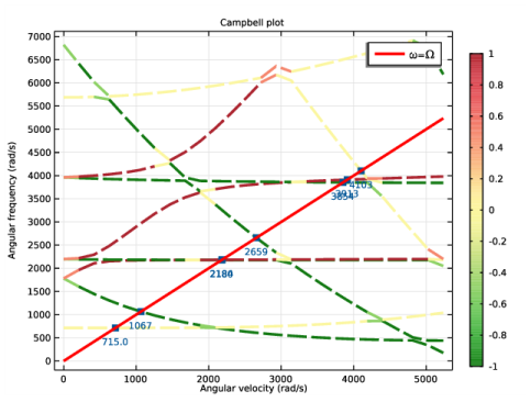
The Campbell plot for the same problem modeled using the Solid Rotor, Fixed Frame interface is shown in Figure 7. In this case, the low frequency curves correspond to the disk bending modes.
Figure 7: Campbell diagram computed with the Solid Rotor, Fixed Frame interface.
The whirl plot for the first mode computed with the Beam Rotor interface is shown in Figure 8.
Figure 8: Whirl plot for the first mode computed with the Beam Rotor interface.
The Campbell diagram of the rotor using the Beam Rotor model is shown in Figure 9. The disk bending modes cannot be resolved with a beam rotor due to the kinematic assumptions in the beam formulation.
Figure 9: Campbell diagram computed with the Beam Rotor interface.
The Campbell diagrams computed with the different interfaces look similar. The eigenfrequencies from the beam rotor model may be slightly higher side due to the lower flexibility.
Application Library path: Rotordynamics_Module/Tutorials/campbell_plot_comparison
Modeling Instructions
From the File menu, choose New.
New
In the New window, click  Model Wizard.
Model Wizard
1
In the Model Wizard window, click  3D.
You will compare the modeling of rotor using different interfaces. Add all the rotor interfaces in the physics.
2
In the Select Physics tree, select Structural Mechanics>Rotordynamics>Solid Rotor (rotsld), Structural Mechanics>Rotordynamics>Solid Rotor, Fixed Frame (srotf), and Structural Mechanics>Rotordynamics>Beam Rotor (rotbm).
3
Click Add.
4
Click  Study.
5
In the Select Study tree, select Preset Studies for Selected Physics Interfaces>Eigenfrequency, Prestressed.
6
Start by importing the parameters for modeling the rotor.
Global Definitions
Parameters: General
1
In the Model Builder window, under Global Definitions click Parameters 1.
2
In the Settings window for Parameters, locate the Parameters section.
3
Click  Load from File.
4
5
In the Label text field, type Parameters: General.
Parameters: Stations
1
In the Home toolbar, click  Parameters and choose Add>Parameters.
2
In the Settings window for Parameters, locate the Parameters section.
3
Click  Load from File.
4
5
In the Label text field, type Parameters: Stations.
Parameters: Shaft diameters
1
In the Home toolbar, click  Parameters and choose Add>Parameters.
2
In the Settings window for Parameters, locate the Parameters section.
3
Click  Load from File.
4
5
In the Label text field, type Parameters: Shaft diameters.
Now you will create the rotor geometry based on the imported parameters. Start by creating the 2D axisymmetric geometry of the rotor on a work plane.
Geometry 1
Work Plane 1 (wp1)
In the Geometry toolbar, click  Work Plane.
Work Plane 1 (wp1)>Plane Geometry
In the Model Builder window, click Plane Geometry.
Work Plane 1 (wp1)>Polygon 1 (pol1)
1
In the Work Plane toolbar, click  Polygon.
You can choose to specify the coordinates for the polygons to create the 2D axisymmetric geometry yourself. To quickly create the geometry you can import these coordinates from a file.
2
In the Settings window for Polygon, locate the Coordinates section.
3
Click  Load from File.
4
Work Plane 1 (wp1)
Revolve the 2D axisymmetric geometry to get the full rotor geometry.
Revolve 1 (rev1)
1
In the Model Builder window, under Component 1 (comp1)>Geometry 1 right-click Work Plane 1 (wp1) and choose Revolve.
2
In the Settings window for Revolve, locate the Revolution Axis section.
3
Find the Direction of revolution axis subsection. In the xw text field, type 1.
4
In the yw text field, type 0.
5
Click  Build All Objects.
6
Click the  Zoom Extents button in the Graphics toolbar.
Now create some selections of the rotor and bearings for later use.
Definitions
Beam Rotor
1
In the Definitions toolbar, click  Explicit.
2
In the Settings window for Explicit, locate the Input Entities section.
3
From the Geometric entity level list, choose Edge.
4
Click the  Wireframe Rendering button in the Graphics toolbar.
5
6
Select the Group by continuous tangent check box.
7
In the Label text field, type Beam Rotor.
Journal Bearing 1
1
In the Definitions toolbar, click  Explicit.
2
In the Settings window for Explicit, locate the Input Entities section.
3
From the Geometric entity level list, choose Boundary.
4
5
Select the Group by continuous tangent check box.
6
In the Label text field, type Journal Bearing 1.
Journal Bearing 2
1
Right-click Journal Bearing 1 and choose Duplicate.
2
In the Settings window for Explicit, locate the Input Entities section.
3
Click  Clear Selection.
4
5
In the Label text field, type Journal Bearing 2.
Journal Bearing 3
1
Right-click Journal Bearing 2 and choose Duplicate.
2
In the Settings window for Explicit, locate the Input Entities section.
3
Click  Clear Selection.
4
5
In the Label text field, type Journal Bearing 3.
For a beam rotor, you can specify different diameters between different stations by using as many Rotor Cross Section nodes as rotor segments. To avoid multiple such nodes you can make use of interpolation function for the diameter as a function of the axial coordinate of the rotor. To create the steps in the rotor diameter, you can use a small tolerance near the stations.
Interpolation: rotor dia
1
In the Definitions toolbar, click  Interpolation.
2
In the Settings window for Interpolation, locate the Definition section.
3
Click  Load from File.
4
5
6
In the Label text field, type Interpolation: rotor dia.
7
Locate the Definition section. In the Function name text field, type dia.
8
Locate the Units section. In the Function table, enter the following settings:
9
In the Argument table, enter the following settings:
10
Add Material
1
In the Home toolbar, click  Add Material to open the Add Material window.
2
Go to the Add Material window.
3
In the tree, select Built-in>Structural steel.
4
Click Add to Global Materials in the window toolbar.
5
In the Home toolbar, click  Add Material to close the Add Material window.
Materials
Material Link: Solid
1
In the Model Builder window, under Component 1 (comp1) right-click Materials and choose More Materials>Material Link.
2
In the Settings window for Material Link, type Material Link: Solid in the Label text field.
Material Link: Beam
1
Right-click Material Link: Solid and choose Duplicate.
2
In the Settings window for Material Link, locate the Geometric Entity Selection section.
3
From the Geometric entity level list, choose Edge.
4
From the Selection list, choose Beam Rotor.
5
In the Label text field, type Material Link: Beam.
Solid Rotor (rotsld)
1
In the Model Builder window, under Component 1 (comp1) click Solid Rotor (rotsld).
2
In the Settings window for Solid Rotor, locate the Rotor Speed section.
3
Rotor Axis 1
1
In the Model Builder window, under Component 1 (comp1)>Solid Rotor (rotsld) click Rotor Axis 1.
2
In the Settings window for Rotor Axis, locate the Rotor Axis section.
3
From the Specified by list, choose Edge.
Axis 1
1
In the Model Builder window, click Axis 1.
2
In the Settings window for Axis, locate the Edge Selection section.
3
From the Selection list, choose Beam Rotor.
Fixed Axial Rotation 1
1
Click the  Wireframe Rendering button in the Graphics toolbar.
2
In the Model Builder window, under Component 1 (comp1)>Solid Rotor (rotsld) click Fixed Axial Rotation 1.
3
Journal Bearing 1
1
In the Physics toolbar, click  Boundaries and choose Journal Bearing.
2
In the Settings window for Journal Bearing, locate the Boundary Selection section.
3
From the Selection list, choose Journal Bearing 1.
4
Locate the Bearing Properties section. From the Bearing model list, choose Total spring and damping constant.
5
In the ku table, enter the following settings:
6
In the kθ table, enter the following settings:
Now duplicate the current bearing node to create other bearings.
Journal Bearing 2
1
Right-click Journal Bearing 1 and choose Duplicate.
2
In the Settings window for Journal Bearing, locate the Boundary Selection section.
3
From the Selection list, choose Journal Bearing 2.
4
Locate the Bearing Properties section. In the kθ table, enter the following settings:
Journal Bearing 3
1
Right-click Journal Bearing 2 and choose Duplicate.
2
In the Settings window for Journal Bearing, locate the Boundary Selection section.
3
From the Selection list, choose Journal Bearing 3.
4
Locate the Bearing Properties section. In the kθ table, enter the following settings:
Solid Rotor, Fixed Frame (srotf)
1
In the Model Builder window, under Component 1 (comp1) click Solid Rotor, Fixed Frame (srotf).
2
In the Settings window for Solid Rotor, Fixed Frame, locate the Rotor Speed section.
3
Rotor Axis 1
1
In the Model Builder window, under Component 1 (comp1)>Solid Rotor, Fixed Frame (srotf) click Rotor Axis 1.
2
In the Settings window for Rotor Axis, locate the Rotor Axis section.
3
From the Specified by list, choose Edge.
Axis 1
1
In the Model Builder window, click Axis 1.
2
In the Settings window for Axis, locate the Edge Selection section.
3
From the Selection list, choose Beam Rotor.
Fixed Axial Rotation 1
1
In the Model Builder window, under Component 1 (comp1)>Solid Rotor, Fixed Frame (srotf) click Fixed Axial Rotation 1.
2
Copy the bearing nodes from the Solid Rotor to Solid Rotor, Fixed Frame interface to create similar bearing features.
Solid Rotor (rotsld)
Journal Bearing 1, Journal Bearing 2, Journal Bearing 3
1
In the Model Builder window, under Component 1 (comp1)>Solid Rotor (rotsld), Ctrl-click to select Journal Bearing 1, Journal Bearing 2, and Journal Bearing 3.
2
Solid Rotor, Fixed Frame (srotf)
Journal Bearing 1
In the Model Builder window, under Component 1 (comp1) right-click Solid Rotor, Fixed Frame (srotf) and choose Paste Multiple Items.
Journal Bearing 1, Journal Bearing 2, Journal Bearing 3
1
In the Model Builder window, under Component 1 (comp1)>Solid Rotor, Fixed Frame (srotf), Ctrl-click to select Journal Bearing 1, Journal Bearing 2, and Journal Bearing 3.
2
In the Settings window for Journal Bearing, locate the Bearing Properties section.
3
In the kθ table, enter the following settings:
Journal Bearing 2
1
In the Model Builder window, click Journal Bearing 2.
2
In the Settings window for Journal Bearing, locate the Bearing Properties section.
3
In the kθ table, enter the following settings:
Journal Bearing 3
1
In the Model Builder window, click Journal Bearing 3.
2
In the Settings window for Journal Bearing, locate the Bearing Properties section.
3
In the kθ table, enter the following settings:
Beam Rotor (rotbm)
1
In the Model Builder window, under Component 1 (comp1) click Beam Rotor (rotbm).
2
In the Settings window for Beam Rotor, locate the Edge Selection section.
3
From the Selection list, choose Beam Rotor.
4
Locate the Rotor Speed section. In the text field, type fr.
Rotor Cross Section 1
Use the interpolation function with axial coordinate as an argument to specify the axially varying diameter of the rotor.
1
In the Model Builder window, under Component 1 (comp1)>Beam Rotor (rotbm) click Rotor Cross Section 1.
2
In the Settings window for Rotor Cross Section, locate the Cross-Section Definition section.
3
In the do text field, type dia(x).
Journal Bearing 1
1
In the Physics toolbar, click  Points and choose Journal Bearing.
2
Click the  Go to Default View button in the Graphics toolbar.
3
Click the  Wireframe Rendering button in the Graphics toolbar.
4
5
In the Settings window for Journal Bearing, locate the Bearing Properties section.
6
From the Bearing model list, choose Total spring and damping constant.
7
In the ku table, enter the following settings:
Journal Bearing 2
1
Right-click Journal Bearing 1 and choose Duplicate.
2
In the Settings window for Journal Bearing, locate the Point Selection section.
3
Click  Clear Selection.
4
Journal Bearing 3
1
Right-click Journal Bearing 2 and choose Duplicate.
2
In the Settings window for Journal Bearing, locate the Point Selection section.
3
Click  Clear Selection.
4
Mesh: Solid
1
In the Model Builder window, under Component 1 (comp1) click Mesh 1.
2
In the Settings window for Mesh, type Mesh: Solid in the Label text field.
Create a swept mesh for the solid geometry of the rotor. You can use this mesh for Solid Rotor and Solid Rotor, Fixed Frame interfaces.
Swept 1
In the Mesh toolbar, click  Swept.
Distribution 1
1
Right-click Swept 1 and choose Distribution.
2
In the Settings window for Distribution, locate the Distribution section.
3
In the Number of elements text field, type 30.
4
Click  Build Selected.
Now create another mesh along the axis of the rotor for the Beam Rotor interface.
Mesh: Beam
1
In the Mesh toolbar, click Add Mesh and choose Add Mesh.
2
In the Settings window for Mesh, locate the Physics-Controlled Mesh section.
3
In the table, clear the Use check boxes for Solid Rotor (rotsld) and Solid Rotor, Fixed Frame (srotf).
4
In the Label text field, type Mesh: Beam.
Edge 1
1
In the Mesh toolbar, click  Boundary and choose Edge.
2
In the Settings window for Edge, locate the Edge Selection section.
3
From the Selection list, choose Beam Rotor.
4
Click  Build All.
You will perform separate study for each interface to avoid cluster of modes from different physics into the same solution. Start with study for the Solid Rotor interface.
Study: Solid Rotor
1
In the Model Builder window, click Study 1.
2
In the Settings window for Study, type Study: Solid Rotor in the Label text field.
Parametric Sweep
1
In the Study toolbar, click  Parametric Sweep.
2
In the Settings window for Parametric Sweep, locate the Study Settings section.
3
4
Disable all physics interfaces except Solid Rotor in the study to avoid the assembly of corresponding dofs from these interfaces.
Step 1: Stationary
1
In the Model Builder window, click Step 1: Stationary.
2
In the Settings window for Stationary, locate the Physics and Variables Selection section.
3
Select the Modify model configuration for study step check box.
4
In the tree, select Component 1 (comp1)>Solid Rotor, Fixed Frame (srotf) and Component 1 (comp1)>Beam Rotor (rotbm).
5
Click  Disable in Model.
6
Clear the Modify model configuration for study step check box.
Step 2: Eigenfrequency
1
In the Model Builder window, click Step 2: Eigenfrequency.
2
In the Settings window for Eigenfrequency, locate the Study Settings section.
3
Select the Desired number of eigenfrequencies check box. In the associated text field, type 7.
4
Locate the Physics and Variables Selection section. Select the Modify model configuration for study step check box.
5
In the tree, select Component 1 (comp1)>Solid Rotor, Fixed Frame (srotf), Controls spatial frame and Component 1 (comp1)>Beam Rotor (rotbm).
6
Click  Disable in Model.
7
Clear the Modify model configuration for study step check box.
8
In the Study toolbar, click  Compute.
Results
Mode Shape (rotsld)
The mode shape is a default plot. You can change the eigenfrequency values to look at the different modes. The sixth mode is shown in Figure 2.
1
In the Settings window for 3D Plot Group, locate the Data section.
2
From the Eigenfrequency (Hz) list, choose 1124.1.
3
In the Mode Shape (rotsld) toolbar, click  Plot.
4
Click the  Go to Default View button in the Graphics toolbar.
Whirl (rotsld)
Set the same eigenfrequency value in the default whirl plot to analyze the corresponding whirl shape of the rotor. This plot is shown in Figure 3.
1
In the Model Builder window, click Whirl (rotsld).
2
In the Settings window for 3D Plot Group, locate the Data section.
3
From the Eigenfrequency (Hz) list, choose 1124.1.
4
In the Whirl (rotsld) toolbar, click  Plot.
The Solid Rotor interface has two predefined Campbell plots, one in the corotating frame and the other in the fixed frame. The fixed frame version, as shown in Figure 4, can be compared with the corresponding Campbell plots from other interfaces.
5
In the Home toolbar, click  Add Predefined Plot.
Add Predefined Plot
1
Go to the Add Predefined Plot window.
2
In the tree, select Study: Solid Rotor/Parametric Solutions 1 (sol3)>Solid Rotor>Campbell Plot, Fixed Frame (rotsld).
3
Click Add Plot in the window toolbar.
4
In the Home toolbar, click  Add Predefined Plot.
Results
Campbell Plot, Fixed Frame (rotsld)
1
In the Model Builder window, under Results click Campbell Plot, Fixed Frame (rotsld).
2
In the Settings window for 1D Plot Group, locate the Legend section.
3
From the Position list, choose Upper left.
Study for the Solid Rotor is complete. Add a couple of new studies for the Solid Rotor, Fixed Frame and Beam Rotor interfaces.
Add Study
1
In the Home toolbar, click  Add Study to open the Add Study window.
2
Go to the Add Study window.
3
Find the Studies subsection. In the Select Study tree, select Preset Studies for Selected Physics Interfaces>Eigenfrequency, Prestressed.
4
Find the Physics interfaces in study subsection. In the table, clear the Solve check boxes for Solid Rotor (rotsld) and Beam Rotor (rotbm).
5
Click Add Study in the window toolbar.
6
Find the Studies subsection. In the Select Study tree, select General Studies>Eigenfrequency.
Note that you do not need Eigenfrequency, Prestressed study for the Beam Rotor. The spinning causes stress stiffening in the rotor. In the Solid Rotor and Solid Roor, Fixed Frame interfaces, geometric stiffness due to stress stiffening is captured using a prestressed study. In the Beam Rotor, the gyroscopic moment captures the same effect automatically.
7
Find the Physics interfaces in study subsection. In the table, clear the Solve check boxes for Solid Rotor (rotsld) and Solid Rotor, Fixed Frame (srotf).
8
Click Add Study in the window toolbar.
9
In the Home toolbar, click  Add Study to close the Add Study window.
Study: SRFF
1
In the Model Builder window, click Study 2.
2
In the Settings window for Study, type Study: SRFF in the Label text field.
Parametric Sweep
1
In the Study toolbar, click  Parametric Sweep.
2
In the Settings window for Parametric Sweep, locate the Study Settings section.
3
4
Step 1: Stationary
In this study you will disable all other interfaces except Solid Rotor, Fixed Frame.
1
In the Model Builder window, click Step 1: Stationary.
2
In the Settings window for Stationary, locate the Physics and Variables Selection section.
3
Select the Modify model configuration for study step check box.
4
In the tree, select Component 1 (comp1)>Solid Rotor (rotsld) and Component 1 (comp1)>Beam Rotor (rotbm).
5
Click  Disable in Model.
6
Click to expand the Mesh Selection section. In the table, enter the following settings:
7
Locate the Physics and Variables Selection section. Clear the Modify model configuration for study step check box.
Step 2: Eigenfrequency
1
In the Model Builder window, click Step 2: Eigenfrequency.
2
In the Settings window for Eigenfrequency, locate the Physics and Variables Selection section.
3
Select the Modify model configuration for study step check box.
4
In the tree, select Component 1 (comp1)>Solid Rotor (rotsld), Controls spatial frame and Component 1 (comp1)>Beam Rotor (rotbm).
5
Click  Disable in Model.
6
Click to expand the Mesh Selection section. In the table, enter the following settings:
7
Locate the Study Settings section.
8
Select the Desired number of eigenfrequencies check box. In the associated text field, type 9.
9
In the Study toolbar, click  Compute.
Results
Mode Shape (srotf)
The mode shape is a default plot. Change the eigenfrequency values to analyze different modes. The eighth mode is shown in Figure 5.
1
In the Settings window for 3D Plot Group, locate the Data section.
2
From the Eigenfrequency (Hz) list, choose 633.66.
3
In the Mode Shape (srotf) toolbar, click  Plot.
Whirl (srotf)
Change the eigenfrequency value in the default whirl plot to analyze the corresponding whirl shape shown in Figure 6.
1
In the Model Builder window, click Whirl (srotf).
2
In the Settings window for 3D Plot Group, locate the Data section.
3
From the Eigenfrequency (Hz) list, choose 633.66.
4
In the Whirl (srotf) toolbar, click  Plot.
5
In the Home toolbar, click  Add Predefined Plot.
Add Predefined Plot
1
Go to the Add Predefined Plot window.
2
In the tree, select Study: SRFF/Parametric Solutions 2 (sol32)>Solid Rotor, Fixed Frame>Campbell Plot (srotf).
3
Click Add Plot in the window toolbar.
4
In the Home toolbar, click  Add Predefined Plot.
Results
Campbell Plot (srotf)
The Campbell plot from the Solid Rotor, Fixed Frame interface is shown in Figure 7.
Study: Beam Rotor
1
In the Model Builder window, click Study 3.
2
In the Settings window for Study, type Study: Beam Rotor in the Label text field.
Parametric Sweep
1
In the Study toolbar, click  Parametric Sweep.
2
In the Settings window for Parametric Sweep, locate the Study Settings section.
3
4
Step 1: Eigenfrequency
Disable other interfaces except Beam Rotor interface like previous studies.
1
In the Model Builder window, click Step 1: Eigenfrequency.
2
In the Settings window for Eigenfrequency, locate the Physics and Variables Selection section.
3
Select the Modify model configuration for study step check box.
4
In the tree, select Component 1 (comp1)>Solid Rotor (rotsld) and Component 1 (comp1)>Solid Rotor, Fixed Frame (srotf).
5
Click  Disable in Model.
6
Clear the Modify model configuration for study step check box.
7
In the Study toolbar, click  Compute.
Results
Whirl (rotbm)
The default whirl plot is shown in Figure 8.
1
In the Home toolbar, click  Add Predefined Plot.
Add Predefined Plot
1
Go to the Add Predefined Plot window.
2
In the tree, select Study: Beam Rotor/Parametric Solutions 3 (sol60)>Beam Rotor>Campbell Plot (rotbm).
3
Click Add Plot in the window toolbar.
4
In the Home toolbar, click  Add Predefined Plot.
Results
Campbell Plot (rotbm)
The Campbell plot from the Beam Rotor interface is shown in Figure 9.
1
In the Model Builder window, under Results click Campbell Plot (rotbm).
2
In the Settings window for 1D Plot Group, locate the Legend section.
3
From the Position list, choose Upper left.