PDF

Wicking in a Paper Strip
Introduction
Wicking is the phenomenon that occurs when a dry porous material is put into contact with a fluid: it will absorb fluid due to capillary forces. The absorption will continue until an equilibrium is reached where the gravitational forces balance capillary forces. This example, inspired by Ref. 1, models wicking in a paper-like porous medium.
Model Definition
The model is set up as a 2D model of a paper strip with a rectangular geometry of 12 cm length and 1.5 cm width. The thickness of the strip is defined as 1 mm.
The model solves for air saturation and water pressure. The different material parameters used in this model are taken from Ref. 1 and are presented in Table 1.
m2
The paper strip is initially filled with air with an initial water saturation of  0.01. The Brooks and Corey model for capillary pressure and relative permeabilities is used for the time-dependent simulation. At the side boundaries of the paper strip no water flow and is allowed. The boundary conditions for bottom and top boundaries for Darcy’s law are the atmospheric pressure for water phase at the bottom and the hydrostatic atmospheric pressure minus the capillary pressure at the top. For the phase transport, there is no flux assumed for the air phase at the bottom boundary. At the top boundary, a mass flux for the air phase is defined which results from the pressure gradient given in the Darcy model. In the section Notes About the COMSOL Implementation it is specified how an accurate mass flux can be calculated in COMSOL Multiphysics.
Model Equations
This example uses the multiphysics coupling Multiphase Flow in Porous Media, which couples the Darcy’s Law and Phase Transport in Porous Media interfaces.
The Phase Transport in Porous Media interface follows separate equations for the volume fraction si of the wetting or nonwetting fluid i:
(1)
Here, εp is the porosity, κ is the permeability (m2), κri is the relative permeability (a function of saturation for a given fluid), μi is the fluid’s dynamic viscosity (Pa·s), pi is the pressure (Pa), and ρi is the fluid density (kg/m3) of phase i.
As the sum of the volume fractions of the two phases is 1, the remaining volume fraction is computed from
(2)
The capillary pressure pc is calculated as a function of the saturation of the wetting phase sw (which is s2 in the model) and the entry capillary pressure pec. By using the Brooks and Corey model, the capillary pressure is given by:
(3)
where λp is the pore distribution index.
The relative permeabilities for the wetting and nonwetting phases, based on the Brooks and Corey model, are given by
(4)
(5)
The Darcy’s Law interface combines Darcy’s law with the continuity equation:
(6)
where density ρ and dynamic viscosity μ are average values of the two wetting and nonwetting fluids.
Results and Discussion
A transient simulation of 10 minutes is performed. After 600 s, the paper strip is already soaked with water. Figure 1 shows the water saturation for different times.
Figure 1: Water Saturation in the paper strip after 10, 40, 100, 200, 300, and 400 s.
The water saturation in the paper strip can also be displayed for a full 3D geometry as shown in Figure 2.
Figure 2: Water Saturation (3D) after 200 s.
Figure 3 shows the amount of water that is absorbed by the paper strip as a function of time. It is calculated from the height of the liquid front Hlf. In this example model, the simulation values (solid line) are compared with those calculated from the analytical expression given by the Lucas-Washburn equation (dashed line), where Hlf is defined as
(7)
with γ the surface tension, Rc the pore radius, Θ the contact angle and μw the dynamic viscosity of water. Figure 3 shows that the two curves are in good agreement. Note that both Brooks and Corey model and Lucas–Washburn equation are analytical expression that matches experimental results and analytical expressions. You can directly enter the capillary pressure curve if you have experimental data for it.
Figure 3: Water uptake versus time. Solid line: numerical solution. Dashed line: analytical expression given by the Lucas-Washburn equation.
Notes About the COMSOL Implementation
In this model, the top boundary condition for the Phase Transport in Porous Media interface is a mass flux condition where the mass flux results from the pressure gradient computed using Darcy’s Law. To calculate an accurate mass flux, weak constraints are used.
When using weak constraints in an interface, the Lagrange multipliers are additional dependent variables in that interface. The sign of the Lagrange multiplier is the same as the one used when applying the corresponding quantity explicitly in a flux condition.
For postprocessing, it is important to know that in (axially) symmetric models the Lagrange multipliers are not equal to the reaction flux per area but rather per length and full revolution.
For more information about weak constraints, the calculation of accurate fluxes, and Lagrange multipliers, see the sections Boundary Conditions and Computing Accurate Fluxes in the COMSOL Multiphysics Reference Manual.
Reference
1. R. Masoodi and K.M. Pillai, “Darcy’s Law-Based Model for Wicking in Paper-Like Swelling Porous Media,” AIChE J., vol. 56, pp 2257–2267, 2010.
Application Library path: Porous_Media_Flow_Module/Fluid_Flow/wicking_paper
Modeling Instructions
From the File menu, choose New.
New
In the New window, click  Model Wizard.
Model Wizard
1
In the Model Wizard window, click  2D.
2
In the Select Physics tree, select Fluid Flow>Porous Media and Subsurface Flow>Multiphase Flow in Porous Media.
3
Click Add.
4
Click  Study.
5
In the Select Study tree, select General Studies>Time Dependent.
6
Global Definitions
Parameters 1
1
In the Model Builder window, under Global Definitions click Parameters 1.
Define the parameters for the geometry and the material properties as follows:
2
In the Settings window for Parameters, locate the Parameters section.
3
Definitions
Step 1 (step1)
1
In the Home toolbar, click  Functions and choose Local>Step.
2
In the Settings window for Step, locate the Parameters section.
3
In the Location text field, type 0.9.
4
In the From text field, type 1.
5
In the To text field, type 0.
6
Click to expand the Smoothing section. In the Size of transition zone text field, type 0.2. This step function will be used to define the upper boundary condition for Darcy’s Law. It will ensure that the capillary pressure at the top is set to zero as soon as the paper is soaked with water.
Geometry 1
Rectangle 1 (r1)
1
In the Geometry toolbar, click  Rectangle.
2
In the Settings window for Rectangle, locate the Size and Shape section.
3
In the Width text field, type W0.
4
In the Height text field, type L0.
5
Click  Build All Objects.
Materials
Define the materials in the next step. Introduce them as empty material nodes, first. As soon as the physics has been defined, the material node menu will show you which properties are needed for the simulation. You can then just fill in the values defined in the Parameters list.
Porous Material 1 (pmat1)
In the Model Builder window, under Component 1 (comp1) right-click Materials and choose More Materials>Porous Material.
Water
1
Right-click Materials and choose Blank Material.
2
In the Settings window for Material, type Water in the Label text field.
Air
1
Right-click Materials and choose Blank Material.
2
In the Settings window for Material, type Air in the Label text field.
Darcy’s Law (dl)
1
In the Model Builder window, under Component 1 (comp1) click Darcy’s Law (dl).
2
In the Settings window for Darcy’s Law, locate the Physical Model section.
3
In the dz text field, type th.
4
Click to expand the Discretization section. From the Pressure list, choose Linear.
Pressure 1
1
In the Physics toolbar, click  Boundaries and choose Pressure.
2
Pressure 2
1
In the Physics toolbar, click  Boundaries and choose Pressure.
2
3
In the Settings window for Pressure, locate the Pressure section.
4
In the p0 text field, type -(phtr.pc_s2)*step1(s1)-rho_air*L0*g_const to calculate the hydrostatic pressure minus the capillary pressure at the upper boundary. The capillary pressure is set to zero when the paper strip is soaked with water by multiplying it with the smoothed step function defined earlier in the model.
The flux at this boundary will be needed as a boundary condition for the Phase Transport in Porous Media interface. Therefore, weak constraints are used to assure an accurate flux calculation (see the section Notes About the COMSOL Implementation). To activate them, follow the instructions below:
5
Click the  Show More Options button in the Model Builder toolbar.
6
In the Show More Options dialog box, in the tree, select the check box for the node Physics>Advanced Physics Options.
7
8
In the Settings window for Pressure, click to expand the Constraint Settings section.
9
From the Apply reaction terms on list, choose Individual dependent variables.
10
Select the Use weak constraints check box.
Phase Transport in Porous Media (phtr)
1
In the Model Builder window, under Component 1 (comp1) click Phase Transport in Porous Media (phtr).
2
In the Settings window for Phase Transport in Porous Media, locate the Gravity Effects section.
3
Select the Include gravity check box.
Phase and Porous Media Transport Properties 1
1
In the Model Builder window, under Component 1 (comp1)>Phase Transport in Porous Media (phtr) click Phase and Porous Media Transport Properties 1.
2
In the Settings window for Phase and Porous Media Transport Properties, locate the Capillary Pressure section.
3
From the Capillary pressure model list, choose Brooks and Corey.
4
Click to expand the Equation section. Locate the Capillary Pressure section. In the pec text field, type pec.
5
In the λp text field, type lp.
6
Locate the Phase 1 Properties section. From the Fluid s1 list, choose Water (mat1).
7
Locate the Phase 2 Properties section. From the Fluid s2 list, choose Air (mat2).
Initial Values 1
1
In the Model Builder window, click Initial Values 1.
2
In the Settings window for Initial Values, locate the Initial Values section.
3
In the s0,s2 text field, type 0.99.
Mass Flux 1
1
In the Physics toolbar, click  Boundaries and choose Mass Flux.
2
In the Settings window for Mass Flux, locate the Mass Flux section.
3
Select the Phase s2 check box.
4
5
In the q0,s2 text field, type p_lm[kg/m/s]/th. Here p_lm is the Lagrange multiplier representing the flux at the boundary (see the section Notes About the COMSOL Implementation). It was introduced as an additional variable to solve for when the weak constraints were activated for this boundary in the Darcy’s Law interface. As the Lagrange multiplier does not take into account the thickness of the paper strip the flux has to be divided by it.
Now, you can fill in the missing material properties.
Materials
Porous Material 1 (pmat1)
1
In the Model Builder window, under Component 1 (comp1)>Materials click Porous Material 1 (pmat1).
2
In the Settings window for Porous Material, locate the Porosity section.
3
In the εp text field, type por.
4
Locate the Homogenized Properties section. In the table, enter the following settings:
Water (mat1)
1
In the Model Builder window, click Water (mat1).
2
In the Settings window for Material, locate the Material Contents section.
3
Air (mat2)
1
In the Model Builder window, click Air (mat2).
2
In the Settings window for Material, locate the Material Contents section.
3
Mesh 1
Mapped 1
In the Mesh toolbar, click  Mapped.
Distribution 1
1
Right-click Mapped 1 and choose Distribution.
2
3
In the Settings window for Distribution, locate the Distribution section.
4
In the Number of elements text field, type 1.
Distribution 2
1
In the Model Builder window, right-click Mapped 1 and choose Distribution.
2
3
In the Settings window for Distribution, locate the Distribution section.
4
From the Distribution type list, choose Predefined.
5
In the Number of elements text field, type 200.
6
In the Element ratio text field, type 1000.
7
Click  Build All. The dense mesh at the bottom is needed to resolve the very steep saturation gradient in the initial phase of the process.
Study 1
Now set up the study. The paper strip is fully soaked with water after 10 minutes so this is the end time to choose for the simulation. As there are very steep gradients in the volume fractions of water and air, make sure that the initial time step is small enough by following the instructions below.
Step 1: Time Dependent
1
In the Model Builder window, under Study 1 click Step 1: Time Dependent.
2
In the Settings window for Time Dependent, locate the Study Settings section.
3
In the Output times text field, type range(0,10,600).
Solution 1 (sol1)
1
In the Study toolbar, click  Show Default Solver.
2
In the Model Builder window, expand the Solution 1 (sol1) node, then click Time-Dependent Solver 1.
3
In the Settings window for Time-Dependent Solver, click to expand the Time Stepping section.
4
Select the Initial step check box. In the associated text field, type 0.0001.
5
In the Study toolbar, click  Compute.
Results
A surface plot of the volume fraction of water (s1) and the pressure is generated by default. To group the different surface plots of the water saturation directly in one postprocessing window as shown in Figure 1 follow the steps below:
Water Saturation (grouped)
1
In the Home toolbar, click  Add Plot Group and choose 2D Plot Group.
2
In the Settings window for 2D Plot Group, type Water Saturation (grouped) in the Label text field.
3
Locate the Data section. From the Time (s) list, choose 10.
4
Click to expand the Title section. From the Title type list, choose Manual.
5
In the Title text area, type Water Saturation.
6
Clear the Parameter indicator text field.
Surface 1
1
Right-click Water Saturation (grouped) and choose Surface.
2
In the Settings window for Surface, locate the Data section.
3
From the Dataset list, choose Study 1/Solution 1 (sol1).
4
From the Time (s) list, choose 10.
5
Locate the Coloring and Style section. Click  Change Color Table.
6
In the Color Table dialog box, select Aurora>JupiterAuroraBorealis in the tree.
7
8
In the Settings window for Surface, locate the Coloring and Style section.
9
From the Color table transformation list, choose Reverse.
10
Click to expand the Range section. Select the Manual color range check box.
11
In the Maximum text field, type 1.
12
In the Water Saturation (grouped) toolbar, click  Plot.
Use the Plot Array functionality to create multiple plots next to each other.
Water Saturation (grouped)
1
In the Model Builder window, click Water Saturation (grouped).
2
In the Settings window for 2D Plot Group, click to expand the Plot Array section.
3
Select the Enable check box.
4
In the Relative padding text field, type 0.5.
Surface 2
1
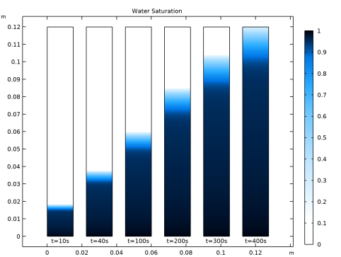
In the Model Builder window, under Results>Water Saturation (grouped) right-click Surface 1 and choose Duplicate.
2
In the Settings window for Surface, locate the Data section.
3
From the Time (s) list, choose 40.
4
Click to expand the Inherit Style section. From the Plot list, choose Surface 1.
Surface 3
1
Right-click Surface 2 and choose Duplicate.
2
In the Settings window for Surface, locate the Data section.
3
From the Time (s) list, choose 100.
Surface 4
1
Right-click Surface 3 and choose Duplicate.
2
In the Settings window for Surface, locate the Data section.
3
From the Time (s) list, choose 200.
Surface 5
1
Right-click Surface 4 and choose Duplicate.
2
In the Settings window for Surface, locate the Data section.
3
From the Time (s) list, choose 300.
Surface 6
1
Right-click Surface 5 and choose Duplicate.
2
In the Settings window for Surface, locate the Data section.
3
From the Time (s) list, choose 400.
Water Saturation (grouped)
In the Model Builder window, click Water Saturation (grouped).
Table Annotation 1
1
In the Water Saturation (grouped) toolbar, click  More Plots and choose Table Annotation.
2
In the Settings window for Table Annotation, locate the Data section.
3
From the Source list, choose Local table.
4
5
Locate the Coloring and Style section. Clear the Show point check box.
6
From the Anchor point list, choose Upper middle.
7
In the Water Saturation (grouped) toolbar, click  Plot.
8
Click the  Zoom Extents button in the Graphics toolbar.
To reproduce Figure 2 create a 3D dataset and use this to plot the water saturation by following the instructions below.
Extrusion 2D 1
1
In the Results toolbar, click  More Datasets and choose Extrusion 2D.
2
In the Settings window for Extrusion 2D, locate the Extrusion section.
3
In the z maximum text field, type th.
4
3D Plot Group 4
1
In the Results toolbar, click  3D Plot Group.
2
In the Settings window for 3D Plot Group, locate the Data section.
3
From the Time (s) list, choose 200.
4
Click to expand the Title section. From the Title type list, choose Manual.
5
In the Title text area, type Water Saturation.
6
In the Parameter indicator text field, type Time=eval(t) s.
Surface 1
1
Right-click 3D Plot Group 4 and choose Surface.
2
In the Settings window for Surface, locate the Coloring and Style section.
3
Click  Change Color Table.
4
In the Color Table dialog box, select Aurora>JupiterAuroraBorealis in the tree.
5
6
In the Settings window for Surface, locate the Coloring and Style section.
7
From the Color table transformation list, choose Reverse.
Water Saturation 3D
1
In the Model Builder window, under Results click 3D Plot Group 4.
2
In the Settings window for 3D Plot Group, type Water Saturation 3D in the Label text field.
3
In the Water Saturation 3D toolbar, click  Plot.
Global Definitions
To compare the simulation results with theoretical values based on the Lucas-Washburn equation (see Figure 3), an additional variable, the height of the liquid front H_lf, is introduced (as in Equation 7) and used to compute the absorbed amount of water as a function of time.
Variables 1
1
In the Model Builder window, right-click Global Definitions and choose Variables.
2
In the Settings window for Variables, locate the Variables section.
3
Definitions
Integration 1 (intop1)
1
In the Definitions toolbar, click  Nonlocal Couplings and choose Integration.
2
Study 1
Now you have to update your solution to get the new variable for all time steps.
1
In the Study toolbar, click  Update Solution.
Results
Global Evaluation 1
1
In the Results toolbar, click  Global Evaluation.
2
In the Settings window for Global Evaluation, locate the Expressions section.
3
4
Click  Evaluate.
Table
1
Go to the Table window.
2
Click Table Graph in the window toolbar.
Results
Water Uptake
1
In the Model Builder window, under Results click 1D Plot Group 5.
2
In the Settings window for 1D Plot Group, type Water Uptake in the Label text field.
Table Graph 1
1
In the Model Builder window, click Table Graph 1.
2
In the Settings window for Table Graph, locate the Coloring and Style section.
3
Find the Line style subsection. From the Line list, choose Cycle.
4
From the Color list, choose Black.
5
From the Width list, choose 2.
6
Click to expand the Legends section. Select the Show legends check box.
7
From the Legends list, choose Manual.
8
Water Uptake
1
In the Model Builder window, click Water Uptake.
2
In the Settings window for 1D Plot Group, locate the Legend section.
3
From the Position list, choose Upper left.
4
In the Water Uptake toolbar, click  Plot.
5
Locate the Plot Settings section.
6
Select the y-axis label check box. In the associated text field, type Absorbed Water (g).
Compare this plot to Figure 3.