PDF

Steam Reformer Geometry
Introduction
Named selections in COMSOL Multiphysics collect geometric entities so that these can easily be reused for any number of model definitions, and are therefore a useful tool for an efficient simulation setup.
The types of selections that are available include the explicit selection features where you can collect individual geometry objects or geometric entities, for example boundaries and edges. You can also create coordinate-based selections to combine entities enclosed by the part of the geometry defined by the volume, area or interval specified in the selection. You can set up both of these selection types either under the Definitions or the Geometry subnodes of a Component node in a model.
In addition to the selection features that you can add to the model tree, you can configure the features under a Geometry node (that is, the operations in the geometry sequence) to automatically create selections that contain the resulting entities from the operation. Geometry operations can also contribute to cumulative selections that are useful for more sophisticated designs where entirely different definitions of selections may be needed in different branches, which are controlled by If nodes of the geometry sequence.
Other selection types include the selection of adjacent geometric entities and Boolean selections, including union, intersection, difference, and complement selections, which can be used to combine any previously defined selections and give you even more flexibility when setting up a model.
Selections that are added under the Definitions node can include geometric entities that exist on the finalized geometry on which you define the physics settings. You can use these selections, for example, for material and physics assignments, when creating a mesh or when creating views for results plots. Selections that you create inside the geometry sequence can, in addition, be used as input to feature nodes downstream of the selection in the sequence. Selections in the geometry sequence thus contain the objects and entities that exist at the current build state of the geometry. They are of help when you want to create robust, parameterized designs in cases when changing parameter values result in significant changes of the topology.
In this tutorial you will leverage selections for creating the parametric geometry for the analysis of a steam reformer and set up the selections needed for the physics definitions. The multiphysics analysis of the steam reformer is described in the model Steam Reformer found in the Chemical Reaction Engineering Module Application Library.
Model Definition
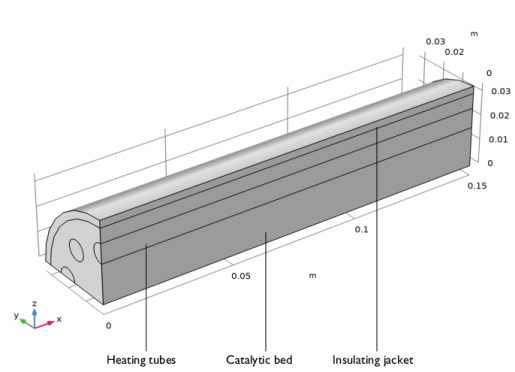
The geometry that represents a quarter of the steam reformer is shown in Figure 1. For each of the regions shown in the figure we will set up selections that contain the corresponding domains in the geometry. We will also define boundary selections for the inlets and outlets, symmetry boundaries, and the interfaces between the domains.
Figure 1: Steam Reformer, quarter.
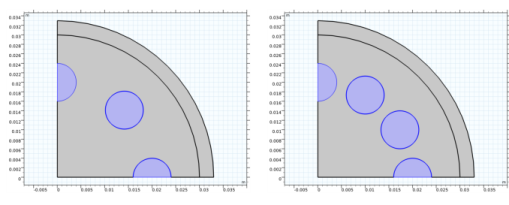
To create the geometry, you start by drawing the cross section on a work plane; see Figure 2, where the number of heating tubes is parameterized.
Figure 2: The cross section of the steam reformer. The number of heating tubes can be changed by a parameter.
After following this tutorial, you will be able to:
-
-
This example describes only the process of creating the geometry sequence. For the physics setup, follow the instructions for the model Steam Reformer in the Chemical Reaction Engineering Module Application Library.
Application Library path: COMSOL_Multiphysics/Geometry_Tutorials/steam_reformer_geometry
Modeling Instructions
From the File menu, choose New.
New
In the New window, click  Blank Model.
Global Definitions
Parameters 1
1
In the Model Builder window, under Global Definitions click Parameters 1.
2
In the Settings window for Parameters, locate the Parameters section.
3
Add Component
In the Home toolbar, click  Add Component and choose 3D.
Geometry 1
Start with drawing the cross section of the geometry on a Work Plane.
Work Plane 1 (wp1)
1
In the Geometry toolbar, click  Work Plane.
2
In the Settings window for Work Plane, locate the Plane Definition section.
3
From the Plane list, choose yz-plane.
4
Click  Show Work Plane.
Work Plane 1 (wp1)>Circle 1 (c1)
1
In the Work Plane toolbar, click  Circle.
2
In the Settings window for Circle, locate the Size and Shape section.
3
In the Radius text field, type jr.
4
In the Sector angle text field, type 90.
5
Click to expand the Layers section. In the table, enter the following settings:
6
Click  Build Selected.
7
Click the  Zoom Extents button in the Graphics toolbar.
Tubes Outlet
1
In the Work Plane toolbar, click  Circle.
2
In the Settings window for Circle, type Tubes Outlet in the Label text field.
3
Locate the Size and Shape section. In the Radius text field, type tr.
4
Locate the Position section. In the yw text field, type pt.
5
Locate the Selections of Resulting Entities section. Select the Resulting objects selection check box.
6
From the Show in 3D list, choose All levels.
With this option selected a selection with a selection with the name of the node will be available for subsequent geometry operations in the geometry sequence of the work plane and the 3D geometry sequence.
Now use the Rotate operation to create a circular array of the heating tubes.
Work Plane 1 (wp1)>Rotate 1 (rot1)
1
In the Work Plane toolbar, click  Transforms and choose Rotate.
2
In the Settings window for Rotate, locate the Input section.
3
From the Input objects list, choose Tubes Outlet.
The range operator makes it easy to define the rotation. In this case the angle between the heating tubes is 360/nt [deg] and we need to generate one quarter of the geometry.
4
Locate the Rotation section. In the Angle text field, type -range(0,360/nt,360/4).
5
Click  Build Selected.
Work Plane 1 (wp1)>Union 1 (uni1)
1
In the Work Plane toolbar, click  Booleans and Partitions and choose Union.
2
In the Settings window for Union, locate the Union section.
3
From the Input objects list, choose Tubes Outlet.
4
Click  Build Selected.
The Compose Boolean operation provides an easy way of combining the geometry objects created so far. An alternative way to get the same results is to use the Union and Intersection Boolean operations.
Work Plane 1 (wp1)>Compose 1 (co1)
1
In the Work Plane toolbar, click  Booleans and Partitions and choose Compose.
2
Click the  Select All button in the Graphics toolbar.
3
In the Settings window for Compose, locate the Compose section.
4
In the Set formula text field, type c1+c1*uni1.
5
Click  Build Selected.
Next, define the selection for the bed inlet that is the face (domain in the work plane) that is adjacent to the heating tubes.
Bed Inlet
1
In the Work Plane toolbar, click  Selections and choose Adjacent Selection.
2
In the Settings window for Adjacent Selection, locate the Input Entities section.
3
4
In the Add dialog box, select Tubes Outlet in the Input selections list.
5
6
In the Settings window for Adjacent Selection, locate the Output Entities section.
7
From the Geometric entity level list, choose Adjacent domains.
8
In the Label text field, type Bed Inlet.
9
Click  Build Selected.
Work Plane 1 (wp1)
1
In the Model Builder window, under Component 1 (comp1)>Geometry 1 click Work Plane 1 (wp1).
2
In the Settings window for Work Plane, locate the Unite Objects section.
3
Clear the Unite objects check box.
4
Locate the Selections of Resulting Entities section. Find the Selections from plane geometry subsection. Select the Show in physics check box, to make the selections from the work plane available for the physics setup.
5
Click  Build Selected.
Extrude the faces from the work plane. The label of the feature node becomes the name of the output selection when you use the Resulting object selections option for the operation.
Jacket
1
In the Geometry toolbar, click  Extrude.
2
In the Settings window for Extrude, type Jacket in the Label text field.
3
Locate the General section. From the Extrude from list, choose Faces.
4
On the object wp1, select Boundary 3 only.
5
From the Input object handling list, choose Keep.
6
Locate the Distances section. In the table, enter the following settings:
7
Locate the Selections of Resulting Entities section. Select the Resulting objects selection check box.
8
From the Show in physics list, choose All levels.
9
Click  Build Selected.
Catalytic Bed
1
In the Geometry toolbar, click  Extrude.
2
In the Settings window for Extrude, type Catalytic Bed in the Label text field.
3
Locate the General section. From the Extrude from list, choose Faces.
4
From the Input faces list, choose Bed Inlet (Work Plane 1).
5
From the Input object handling list, choose Keep.
6
Locate the Distances section. In the table, enter the following settings:
7
Locate the Selections of Resulting Entities section. Select the Resulting objects selection check box.
8
From the Show in physics list, choose All levels.
9
Click  Build Selected.
Heating Tubes
1
In the Geometry toolbar, click  Extrude.
2
In the Settings window for Extrude, type Heating Tubes in the Label text field.
3
Locate the General section. From the Extrude from list, choose Faces.
4
From the Input faces list, choose Tubes Outlet (Work Plane 1).
5
From the Input object handling list, choose Keep.
6
Locate the Distances section. In the table, enter the following settings:
7
Locate the Selections of Resulting Entities section. Select the Resulting objects selection check box.
8
From the Show in physics list, choose All levels.
9
Click  Build Selected.
Form Union (fin)
1
In the Model Builder window, click Form Union (fin).
2
In the Settings window for Form Union/Assembly, click  Build Selected.
3
Click the  Wireframe Rendering button in the Graphics toolbar, to get a better overview of the interior entities.
The geometry of the steam reformer is now complete. In the following we will generate the remaining selections for the simulation setup using selection operations. The technique of defining selections as illustrated in this tutorial is especially useful for more complex geometries where manually selecting many geometric entities can be inefficient. This technique can also provide a robust way for creating selections when running geometric parametric sweeps that change the topology, for example when exploring the effect on the results of the number of heating tubes in this geometry.
Bed/Jacket
1
In the Geometry toolbar, click  Selections and choose Intersection Selection.
2
In the Settings window for Intersection Selection, type Bed/Jacket in the Label text field.
3
Locate the Geometric Entity Level section. From the Level list, choose Boundary.
4
Locate the Input Entities section. Click  Add.
5
In the Add dialog box, in the Selections to intersect list, choose Jacket and Catalytic Bed.
6
Tubes/Bed
1
In the Geometry toolbar, click  Selections and choose Intersection Selection.
2
In the Settings window for Intersection Selection, type Tubes/Bed in the Label text field.
3
Locate the Geometric Entity Level section. From the Level list, choose Boundary.
4
Locate the Input Entities section. Click  Add.
5
In the Add dialog box, in the Selections to intersect list, choose Catalytic Bed and Heating Tubes.
6
Cylinder Selection 1 (cylsel1)
1
In the Geometry toolbar, click  Selections and choose Cylinder Selection.
2
In the Settings window for Cylinder Selection, locate the Geometric Entity Level section.
3
From the Level list, choose Boundary.
4
Locate the Size and Shape section. In the Outer radius text field, type inf.
5
In the Start angle text field, type 180.
6
In the End angle text field, type 90.
7
Locate the Axis section. From the Axis type list, choose x-axis.
8
Locate the Output Entities section. From the Include entity if list, choose Entity inside cylinder.
Jacket Symmetry
1
In the Geometry toolbar, click  Selections and choose Intersection Selection.
2
In the Settings window for Intersection Selection, type Jacket Symmetry in the Label text field.
3
Locate the Geometric Entity Level section. From the Level list, choose Boundary.
4
Locate the Input Entities section. Click  Add.
5
In the Add dialog box, in the Selections to intersect list, choose Jacket and Cylinder Selection 1.
6
Tubes Symmetry
1
In the Geometry toolbar, click  Selections and choose Intersection Selection.
2
In the Settings window for Intersection Selection, type Tubes Symmetry in the Label text field.
3
Locate the Geometric Entity Level section. From the Level list, choose Boundary.
4
Locate the Input Entities section. Click  Add.
5
In the Add dialog box, in the Selections to intersect list, choose Heating Tubes and Cylinder Selection 1.
6
Bed Symmetry
1
In the Geometry toolbar, click  Selections and choose Intersection Selection.
2
In the Settings window for Intersection Selection, type Bed Symmetry in the Label text field.
3
Locate the Geometric Entity Level section. From the Level list, choose Boundary.
4
Locate the Input Entities section. Click  Add.
5
In the Add dialog box, in the Selections to intersect list, choose Catalytic Bed and Cylinder Selection 1.
6
Inlets and Outlets
1
In the Geometry toolbar, click  Selections and choose Difference Selection.
2
In the Settings window for Difference Selection, type Inlets and Outlets in the Label text field.
3
Locate the Geometric Entity Level section. From the Level list, choose Boundary.
4
Locate the Input Entities section. Click  Add.
5
In the Add dialog box, in the Selections to add list, choose Catalytic Bed and Heating Tubes.
6
7
In the Settings window for Difference Selection, locate the Input Entities section.
8
9
In the Add dialog box, in the Selections to subtract list, choose Bed/Jacket, Tubes/Bed, Tubes Symmetry, and Bed Symmetry.
10
Tubes Inlet
1
In the Geometry toolbar, click  Selections and choose Difference Selection.
2
In the Settings window for Difference Selection, type Tubes Inlet in the Label text field.
3
Locate the Geometric Entity Level section. From the Level list, choose Boundary.
4
Locate the Input Entities section. Click  Add.
5
In the Add dialog box, select Inlets and Outlets in the Selections to add list.
6
7
In the Settings window for Difference Selection, locate the Input Entities section.
8
9
In the Add dialog box, in the Selections to subtract list, choose Tubes Outlet (Work Plane 1) and Catalytic Bed.
10
Bed Outlet
1
In the Geometry toolbar, click  Selections and choose Difference Selection.
2
In the Settings window for Difference Selection, type Bed Outlet in the Label text field.
3
Locate the Geometric Entity Level section. From the Level list, choose Boundary.
4
Locate the Input Entities section. Click  Add.
5
In the Add dialog box, select Inlets and Outlets in the Selections to add list.
6
7
In the Settings window for Difference Selection, locate the Input Entities section.
8
9
In the Add dialog box, in the Selections to subtract list, choose Bed Inlet (Work Plane 1) and Heating Tubes.
10
Jacket/Ambient
1
In the Geometry toolbar, click  Selections and choose Explicit Selection.
2
In the Settings window for Explicit Selection, type Jacket/Ambient in the Label text field.
3
Locate the Entities to Select section. From the Geometric entity level list, choose Boundary.
4
On the object fin, select Boundary 12 only.