PDF

Busbar Assembly Geometry — with Geometry Parts
Introduction
Geometry parts provide a way to organize, parameterize, and reuse geometries that you create in COMSOL Multiphysics. They can be used to simplify geometry creation by providing easy-to-use parts with a number of parameters for tailoring the part’s shape or dimension when added to a COMSOL Multiphysics geometry.
To create the geometry in a part you use geometry operations just as you would normally do, but these are added to the local geometry sequence of the part. To parameterize the geometry you can define a number of input parameters that will be available when a part instance is inserted into a geometry sequence. In addition, local parameters can help when only local parameterization is needed.
Just as when creating any regular geometry, you can use selections in geometry parts to simplify not only the geometry generation, but also material and physics assignment. You can access selections that you have defined in a part sequence both locally within its sequence or when inserting a part instance into a geometry sequence.
An advantage of breaking up complex geometries with many objects into geometry parts is that you can work in a local coordinate system when creating the geometry within each part. When you are inserting the part into a geometry sequence, you can position it by specifying the coordinates, or by matching a coordinate system defined in the part with a coordinate system in the geometry.
If you create a number of useful geometry parts, it is a good idea to collect them in a user-defined part library. This way you can easily reuse your parts or share them with colleagues.
Follow this tutorial to create the busbar geometry used in the model Electrical Heating in a Busbar Assembly, while learning more about how to:
Busbar Assembly Geometry — with Group Nodes is the second part of this tutorial that describes how to organize a geometry sequence with a folder-like structure. The two tutorials in this series complement each other, and show methods to structure more complex geometry sequences.
Model Definition
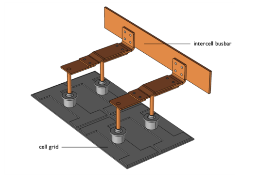
This example contains the detailed steps to create the parameterized geometry used for the model Electrical Heating in a Busbar Assembly. The geometry for this model, displayed in Figure 1, includes the coupling components for one cell, and a section of the intercell busbar that is connected to a cell grid.
Figure 1: The busbar assembly.
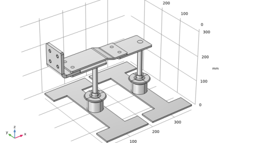
Each component of the busbar is created as a separate geometry part, and a geometry part is also created for the components displayed in Figure 2.
Figure 2: Subunit of the busbar, created in a geometry part.
This example describes only the process of creating the geometry sequence. For the physics setup, follow the instructions in Electrical Heating in a Busbar Assembly.
Application Library path: COMSOL_Multiphysics/Geometry_Tutorials/busbar_assembly_geometry
Modeling Instructions
COMSOL Desktop
1
From the File menu, choose Open.
2
This file contains all but two of the geometry parts for the busbar. In the following you will create the remaining parts and build the busbar geometry. First, check where the geometry parts appear in the model tree.
3
In the Model Builder window, first expand the Global Definitions node, then the Geometry Parts node.
The geometry parts that appear here are not attached to a specific model component, but can be inserted into the geometry sequence of any model component of the appropriate space dimension. To edit the geometry sequence for a part you can expand the part’s node.
Global Definitions
Continue by adding a new geometry part.
Angle connector
1
In the Model Builder window, right-click Global Definitions and choose Geometry Parts>3D Part.
2
In the Settings window for Part, type Angle connector in the Label text field.
3
Locate the Input Parameters section. In the table, enter the following settings:
The parameters listed here are available within the part, and can also be specified with new values when you insert the part into a geometry sequence.
4
Locate the Units section. From the Length unit list, choose mm.
Local Parameters
1
In the Geometry toolbar, click  Programming and choose Local Parameters.
Local parameters are only available within the part. However, they can be defined by expressions containing input parameters.
2
In the Settings window for Local Parameters, locate the Local Parameters section.
3
Create the geometry of the angle connector as the intersection of two solid objects: the extrusion of the side view and the extrusion of the top view. Continue by drawing and extruding the side view.
Work Plane 1 (wp1)
1
In the Geometry toolbar, click  Work Plane.
2
In the Settings window for Work Plane, locate the Plane Definition section.
3
From the Plane list, choose zx-plane.
4
Locate the Part Instances section. Clear the Show work plane in instances check box.
Work Plane 1 (wp1)>Plane Geometry
In the Model Builder window, click Plane Geometry.
Work Plane 1 (wp1)>Polygon 1 (pol1)
1
In the Work Plane toolbar, click  Polygon.
2
In the Settings window for Polygon, locate the Coordinates section.
3
4
Click  Build Selected.
View 26
Add Fillets to the corners.
Work Plane 1 (wp1)>Fillet 1 (fil1)
1
In the Work Plane toolbar, click  Fillet.
2
On the object pol1, select Points 2 and 6 only.
3
In the Settings window for Fillet, locate the Radius section.
4
In the Radius text field, type 20[mm].
5
Click  Build Selected.
Work Plane 1 (wp1)>Fillet 2 (fil2)
1
In the Work Plane toolbar, click  Fillet.
2
On the object fil1, select Points 5 and 6 only.
3
In the Settings window for Fillet, locate the Radius section.
4
In the Radius text field, type 20[mm]-a_c_h_part.
5
Click  Build Selected.
Extrude 1 (ext1)
1
In the Model Builder window, under Global Definitions>Geometry Parts>Angle connector right-click Work Plane 1 (wp1) and choose Extrude.
2
In the Settings window for Extrude, locate the Distances section.
3
4
Click  Build Selected.
The extruded solid for the side view is now ready. Continue by creating the solid for the top view.
Work Plane 2 (wp2)
1
In the Geometry toolbar, click  Work Plane.
2
In the Settings window for Work Plane, locate the Part Instances section.
3
Clear the Show work plane in instances check box.
Work Plane 2 (wp2)>Plane Geometry
In the Model Builder window, click Plane Geometry.
Work Plane 2 (wp2)>Rectangle 1 (r1)
1
In the Work Plane toolbar, click  Rectangle.
2
In the Settings window for Rectangle, locate the Size and Shape section.
3
In the Width text field, type c_g_w_part/2+b_di_part*2.
4
In the Height text field, type a_c_w_part.
5
Click  Build Selected.
Work Plane 2 (wp2)>Fillet 1 (fil1)
1
In the Work Plane toolbar, click  Fillet.
2
On the object r1, select Points 1–4 only.
3
In the Settings window for Fillet, locate the Radius section.
4
In the Radius text field, type 5[mm].
5
Click  Build Selected.
Work Plane 2 (wp2)>Circle 1 (c1)
1
In the Work Plane toolbar, click  Circle.
2
In the Settings window for Circle, locate the Size and Shape section.
3
In the Radius text field, type b_r_part.
4
Locate the Position section. In the xw text field, type b_di_part.
5
In the yw text field, type a_c_w_part/4.
6
Click  Build Selected.
Work Plane 2 (wp2)>Array 1 (arr1)
1
In the Work Plane toolbar, click  Transforms and choose Array.
2
3
In the Settings window for Array, locate the Size section.
4
In the xw size text field, type 2.
5
In the yw size text field, type 2.
6
Locate the Displacement section. In the xw text field, type c_g_w_part/2.
7
In the yw text field, type a_c_w_part/2.
Work Plane 2 (wp2)>Difference 1 (dif1)
1
In the Work Plane toolbar, click  Booleans and Partitions and choose Difference.
2
3
In the Settings window for Difference, locate the Difference section.
4
Find the Objects to subtract subsection. Click to select the  Activate Selection toggle button.
5
Select the objects arr1(1,1), arr1(1,2), arr1(2,1), and arr1(2,2) only.
6
Click  Build Selected.
Extrude 2 (ext2)
1
In the Model Builder window, under Global Definitions>Geometry Parts>Angle connector right-click Work Plane 2 (wp2) and choose Extrude.
2
In the Settings window for Extrude, locate the Distances section.
3
4
Click  Build Selected.
Intersection 1 (int1)
1
In the Geometry toolbar, click  Booleans and Partitions and choose Intersection.
2
Click in the Graphics window and then press Ctrl+A to select both objects.
3
In the Settings window for Intersection, locate the Selections of Resulting Entities section.
4
Select the Resulting objects selection check box, to access this selection from an instance of the part inserted into a geometry sequence.
5
Click  Build Selected.
For easy positioning of this connector part, create two Work Planes and orient the associated coordinate system.
Elbow connector Position
1
In the Geometry toolbar, click  Work Plane.
2
In the Settings window for Work Plane, type Elbow connector Position in the Label text field.
3
Locate the Plane Definition section. From the Plane type list, choose Transformed.
4
From the Work plane to transform list, choose Work Plane 2 (wp2).
5
Find the Displacement subsection. In the xw text field, type c_g_w_part/2+b_di_part.
6
In the yw text field, type a_c_w_part/4.
7
In the zw text field, type e_c_h_part.
Bolt Position
1
In the Geometry toolbar, click  Work Plane.
2
In the Settings window for Work Plane, type Bolt Position in the Label text field.
3
Locate the Plane Definition section. From the Plane type list, choose Transformed.
4
From the Work plane to transform list, choose Work Plane 2 (wp2).
5
Find the Displacement subsection. In the xw text field, type b_di_part.
6
In the yw text field, type a_c_w_part/4.
7
Click the  Zoom Extents button in the Graphics toolbar.
The geometry part for the angle connector is now ready. We will continue with adding one more geometry part where we will insert geometry parts to built a repeating subassembly of the busbar.
Anode top assembly
1
In the Model Builder window, under Global Definitions right-click Geometry Parts and choose 3D Part.
2
In the Settings window for Part, type Anode top assembly in the Label text field.
3
Locate the Input Parameters section. In the table, enter the following settings:
4
Locate the Units section. From the Length unit list, choose mm.
Local Parameters
1
In the Geometry toolbar, click  Programming and choose Local Parameters.
2
In the Settings window for Local Parameters, locate the Local Parameters section.
3
Spine 1 (pi1)
1
In the Geometry toolbar, click  Parts and choose Spine.
2
In the Settings window for Part Instance, click to expand the Domain Selections section.
3
Click New Cumulative Selection.
Cumulative selections are useful when we want the output of several geometry operations to contribute to a selection. Here the cumulative selections will collect the domains for assigning the different materials.
4
In the New Cumulative Selection dialog box, type Titanium in the Name text field.
5
6
In the Settings window for Part Instance, locate the Domain Selections section.
7
8
Click  Highlight Result to make it easier to identify the output of the various features.
9
Click  Build Selected.
Central column 1 (pi2)
1
In the Geometry toolbar, click  Parts and choose Central column.
2
In the Settings window for Part Instance, locate the Input Parameters section.
3
4
Locate the Domain Selections section. In the table, enter the following settings:
5
Click  Build Selected.
To position the part for the central column at the center of the spine, use a coordinate system defined by a work plane the geometry part for the spine.
Spine
1
In the Model Builder under Geometry Parts, expand Spine.
2
Select Central column Position to see where the work plane is located.
Central column Position (wp2)
Returning to the geometry sequence of the Anode top assembly, we can use this work plane to position the part for the central column.
Anode top assembly
Central column 1 (pi2)
1
In the Model Builder window, expand the Global Definitions>Geometry Parts>Spine node, then click Global Definitions>Geometry Parts>Anode top assembly>Central column 1 (pi2).
2
In the Settings window for Part Instance, locate the Position and Orientation of Output section.
3
Find the Coordinate system to match subsection. From the Take work plane from list, choose Spine 1 (pi1).
4
From the Work plane list, choose Central column Position (wp2).
5
Click  Build Selected.
Rod 1 (pi3)
1
In the Geometry toolbar, click  Parts and choose Rod.
2
In the Settings window for Part Instance, locate the Position and Orientation of Output section.
3
Find the Coordinate system to match subsection. From the Take work plane from list, choose Central column 1 (pi2).
4
From the Work plane list, choose Rod Position (wp2).
5
Locate the Input Parameters section. In the table, enter the following settings:
6
Locate the Domain Selections section. Click New Cumulative Selection.
7
In the New Cumulative Selection dialog box, type Copper in the Name text field.
8
9
In the Settings window for Part Instance, locate the Domain Selections section.
10
11
Click  Build Selected.
Rod connector 1 (pi4)
1
In the Geometry toolbar, click  Parts and choose Rod connector.
2
In the Settings window for Part Instance, locate the Position and Orientation of Output section.
3
Find the Coordinate system to match subsection. From the Take work plane from list, choose Rod 1 (pi3).
4
From the Work plane list, choose Rod connector Position (wp1).
5
Locate the Input Parameters section. In the table, enter the following settings:
6
Locate the Domain Selections section. In the table, enter the following settings:
7
Click  Build Selected.
8
Click the  Zoom Extents button in the Graphics toolbar.
Copy 1 (copy1)
To obtain another copy of the already inserted geometry parts you will use the Copy operation.
1
In the Geometry toolbar, click  Transforms and choose Copy.
2
Click the  Select All button in the Graphics toolbar.
3
In the Settings window for Copy, locate the Displacement section.
4
In the x text field, type c_g_w_asm/2.
5
Click  Build Selected.
Elbow connector 1 (pi5)
1
In the Geometry toolbar, click  Parts and choose Elbow connector.
2
In the Settings window for Part Instance, locate the Position and Orientation of Output section.
3
Find the Coordinate system in part subsection. From the Work plane in part list, choose Rod connector Position (wp4).
4
Find the Coordinate system to match subsection. From the Take work plane from list, choose Rod connector 1 (pi4).
5
From the Work plane list, choose Elbow connector Position (wp2).
6
Find the Rotation subsection. In the Rotation angle text field, type 90[deg].
7
Locate the Input Parameters section. In the table, enter the following settings:
8
Locate the Domain Selections section. In the table, enter the following settings:
9
Click to expand the Point Selections section. In the table, enter the following settings:
10
Click  Build Selected.
11
Click the  Zoom Extents button in the Graphics toolbar.
Angle connector 1 (pi6)
1
In the Geometry toolbar, click  Parts and choose Angle connector.
2
In the Settings window for Part Instance, locate the Input Parameters section.
3
4
Locate the Position and Orientation of Output section. Find the Coordinate system in part subsection. From the Work plane in part list, choose Elbow connector Position (wp3).
5
Find the Coordinate system to match subsection. From the Take work plane from list, choose Elbow connector 1 (pi5).
6
From the Work plane list, choose Angle connector Position (wp6).
7
Locate the Domain Selections section. In the table, enter the following settings:
8
Click  Build Selected.
Bolt small
1
In the Geometry toolbar, click  Parts and choose Bolt.
2
In the Settings window for Part Instance, type Bolt small in the Label text field.
3
Locate the Input Parameters section. In the table, enter the following settings:
4
Locate the Position and Orientation of Output section. Find the Coordinate system to match subsection. From the Take work plane from list, choose Angle connector 1 (pi6).
5
From the Work plane list, choose Bolt Position (wp4).
6
Find the Displacement subsection. In the zw text field, type -r_c_h_asm.
7
Locate the Domain Selections section. In the table, enter the following settings:
8
Click  Build Selected.
Bolt large
1
In the Geometry toolbar, click  Parts and choose Bolt.
2
In the Settings window for Part Instance, type Bolt large in the Label text field.
3
Locate the Input Parameters section. In the table, enter the following settings:
4
Locate the Position and Orientation of Output section. Find the Coordinate system to match subsection. From the Take work plane from list, choose Elbow connector 1 (pi5).
5
From the Work plane list, choose Rod connector Position (wp4).
6
Find the Displacement subsection. In the zw text field, type -r_c_h_asm.
7
Locate the Domain Selections section. In the table, enter the following settings:
8
Click  Build Selected.
Mirror 1 (mir1)
1
In the Geometry toolbar, click  Transforms and choose Mirror.
2
Select the objects pi7 and pi8 only.
3
In the Settings window for Mirror, locate the Input section.
4
Select the Keep input objects check box.
5
Locate the Point on Plane of Reflection section. In the y text field, type 190[mm], which is half of the length of the spine.
6
Locate the Normal Vector to Plane of Reflection section. In the y text field, type 1.
7
In the z text field, type 0.
8
Click  Build Selected.
Next, add a work plane that will help with the positioning of this part.
Intercell busbar Position
1
In the Geometry toolbar, click  Work Plane.
2
In the Settings window for Work Plane, type Intercell busbar Position in the Label text field.
3
Locate the Plane Definition section. From the Plane type list, choose Transformed.
4
From the Take work plane from list, choose Elbow connector 1 (pi5).
5
From the Work plane to transform list, choose Intercell busbar Position (wp5).
6
Click  Build Selected.
Finally, set up a selection that includes all objects in this geometry part. It will come in handy when building the busbar geometry.
Box Selection 1 (boxsel1)
1
In the Geometry toolbar, click  Selections and choose Box Selection.
2
In the Settings window for Box Selection, locate the Geometric Entity Level section.
3
From the Level list, choose Object.
4
Click the  Zoom Extents button in the Graphics toolbar.
Global Definitions
All geometry parts are now ready. Next add the global parameters for the dimensions to control in the parametric sweep. Then, add a 3D model component where you can build the busbar geometry.
Parameters 1
1
In the Model Builder window, under Global Definitions click Parameters 1.
2
In the Settings window for Parameters, locate the Parameters section.
3
Add Component
In the Home toolbar, click  Add Component and choose 3D.
Geometry 1
1
In the Settings window for Geometry, locate the Units section.
2
From the Length unit list, choose mm.
Cell grid top 1 (pi1)
1
In the Geometry toolbar, click  Parts and choose Cell grid top.
2
In the Settings window for Part Instance, click to expand the Domain Selections section.
3
Click New Cumulative Selection.
4
In the New Cumulative Selection dialog box, Define Cumulative Selections for the two materials to collect all parts with the same material.
5
type Titanium in the Name text field.
6
7
In the Settings window for Part Instance, locate the Domain Selections section.
8
Click New Cumulative Selection.
9
In the New Cumulative Selection dialog box, type Copper in the Name text field.
10
11
In the Settings window for Part Instance, locate the Domain Selections section.
12
13
Click to expand the Boundary Selections section. In the table, enter the following settings:
14
Click  Build Selected.
Anode top assembly 1 (pi2)
1
In the Geometry toolbar, click  Parts and choose Anode top assembly.
2
In the Settings window for Part Instance, locate the Input Parameters section.
3
4
Locate the Position and Orientation of Output section. Find the Coordinate system to match subsection. From the Take work plane from list, choose Cell grid top 1 (pi1).
5
From the Work plane list, choose Spine Position (wp1).
6
Click to expand the Object Selections section. In the table, enter the following settings:
7
Locate the Domain Selections section. In the table, enter the following settings:
8
Click to expand the Point Selections section. In the table, enter the following settings:
9
Click  Build Selected.
Move 1 (mov1)
1
In the Geometry toolbar, click  Transforms and choose Move.
2
In the Settings window for Move, locate the Input section.
3
From the Input objects list, choose Box Selection 1 (Anode top assembly 1).
4
Locate the Displacement section. In the y text field, type 0 -400[mm]. By using a displacement vector, the input objects are moved to each of the values specified by the vector.
5
Click  Build Selected.
Intercell busbar 1 (pi3)
1
In the Geometry toolbar, click  Parts and choose Intercell busbar.
2
In the Settings window for Part Instance, locate the Input Parameters section.
3
4
Locate the Position and Orientation of Output section. Find the Coordinate system in part subsection. From the Work plane in part list, choose Elbow connector Position (wp2).
5
Find the Coordinate system to match subsection. From the Take work plane from list, choose Anode top assembly 1 (pi2).
6
From the Work plane list, choose Intercell busbar Position (wp1).
7
Locate the Domain Selections section. In the table, enter the following settings:
8
Locate the Boundary Selections section. In the table, enter the following settings:
9
Click  Build Selected.
Bolt medium
1
In the Geometry toolbar, click  Parts and choose Bolt.
2
In the Settings window for Part Instance, type Bolt medium in the Label text field.
3
Locate the Input Parameters section. In the table, enter the following settings:
4
Locate the Position and Orientation of Output section. Find the Rotation subsection. From the Axis type list, choose yw-axis.
5
In the Rotation angle text field, type 90.
6
Locate the Domain Selections section. In the table, enter the following settings:
Move 2 (mov2)
Position the bolt by adding a Move transform operation, and using the option to specify the positions to move to by selecting vertices.
1
In the Geometry toolbar, click  Transforms and choose Move.
2
3
In the Settings window for Move, locate the Displacement section.
4
From the Specify list, choose Positions.
5
Find the Vertex to move subsection. Click to select the  Activate Selection toggle button.
6
On the object pi4, select Point 1 only.
7
From the Vertices to move to list, choose Bolt medium Position (Elbow connector 1) (Anode top assembly 1).
8
Click  Build Selected.
Form Union (fin)
1
In the Model Builder window, click Form Union (fin).
2
In the Settings window for Form Union/Assembly, click  Build Selected.
3
Click the  Zoom Extents button in the Graphics toolbar.
As the busbar geometry is now ready, set up selections to use for the physics definitions.
Adjacent Selection 1 (adjsel1)
1
In the Geometry toolbar, click  Selections and choose Adjacent Selection.
2
In the Settings window for Adjacent Selection, locate the Input Entities section.
3
4
In the Add dialog box, in the Input selections list, choose Titanium and Copper.
5
6
In the Settings window for Adjacent Selection, click  Build Selected.
Heat flux boundaries
1
In the Geometry toolbar, click  Selections and choose Difference Selection.
2
In the Settings window for Difference Selection, type Heat flux boundaries in the Label text field.
3
Locate the Geometric Entity Level section. From the Level list, choose Boundary.
4
Locate the Input Entities section. Click  Add.
5
In the Add dialog box, select Adjacent Selection 1 in the Selections to add list.
6
7
In the Settings window for Difference Selection, locate the Input Entities section.
8
9
In the Add dialog box, in the Selections to subtract list, choose Electrolyte boundary (Cell grid top 1) and Grounded boundary (Intercell busbar 1).
10