PDF

Swept Meshing of a Bracket Geometry
Introduction
Using swept meshing in COMSOL Multiphysics, you can create 3D meshes of prism and hexahedral elements. A swept mesh is an example of a semistructured mesh because it is structured in the sweep direction and can be either structured or unstructured orthogonally to the sweep direction. The swept mesher sweeps a face mesh along a domain to generate layers of mesh elements from a source to a destination. Both the source and destination can consist of several connected faces, as long as each destination face corresponds to at least one source face, and each source face corresponds to exactly one destination face or to a subset of it. The faces that connect the source to the destination are called the linking faces.
The swept mesher can automatically analyze the topology of a domain to determine the source, destination, and linking faces, as long as the geometry satisfies some criteria. In addition to the just mentioned requirements on the source and destination faces, the source and destination must also be opposite each other in the domain’s topology. The domain must also be bounded by one shell, that is, holes are allowed only if they penetrate both the source and destination. Finally, the cross section of the domain along the direction of the sweep must be topologically constant.
This tutorial demonstrates how to create a swept mesh for a geometry that initially does not satisfy the requirements for swept meshing. You will learn how to use partitioning tools and virtual geometry operations to create domains for swept meshing, how to combine swept and tetrahedral meshes, and how to generate mesh plots to view the various element types.
Model Definition
The geometry shown in Figure 1 represents a bracket, which can be used to install an actuator that is mounted on a pin placed between the two large holes in the bracket arms.
Figure 1: The geometry of the bracket used in this tutorial.
For a structural mechanics analysis of the bracket it is possible to create a free tetrahedral mesh, but for a geometry such as this with large flat regions it can be more efficient to create a swept mesh, or a swept mesh combined with tetrahedron mesh for the regions around the fillets.
If you are interested in tutorials for modeling structural mechanics problems using this geometry, look for the series of models titled “Bracket” under Tutorials in the Structural Mechanics Module Application Library. Note, however, that solving these models requires additional licenses.
Application Library path: COMSOL_Multiphysics/Meshing_Tutorials/bracket_swept_mesh
Modeling Instructions
From the File menu, choose New.
New
In the New window, click  Model Wizard.
Model Wizard
1
In the Model Wizard window, click  3D.
2
Geometry 1
Import 1 (imp1)
The bracket geometry for this tutorial has been saved in the COMSOL MPHBIN-format.
1
In the Home toolbar, click  Import.
2
In the Settings window for Import, locate the Import section.
3
Click  Browse.
4
5
Click  Import.
Mesh 1
Swept 1
1
In the Mesh toolbar, click  Swept.
2
In the Settings window for Swept, click to expand the Sweep Method section.
3
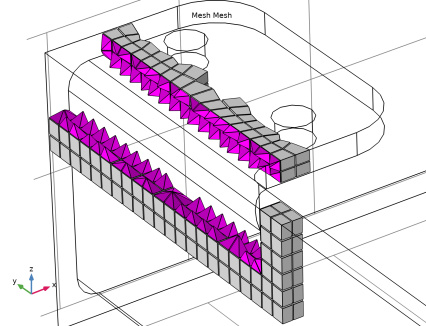
From the Face meshing method list, choose Triangular (generate prisms) to create a swept prism mesh. This will make it easier to see in which direction the mesh is swept.
4
In the Settings window for Swept, click Build All.
The swept mesher fails, since the geometry does not satisfy the requirements for generating a swept mesh. By partitioning the geometry we can create several domains that are possible to generate swept mesh for.
5
In the Error dialog box, click OK.
Geometry 1
Partition Domains 1 (pard1)
1
In the Geometry toolbar, click  Booleans and Partitions and choose Partition Domains.
2
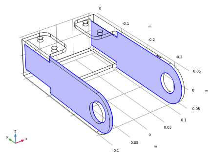
On the object imp1, select Domain 1 only.
3
In the Settings window for Partition Domains, locate the Partition Domains section.
4
From the Partition with list, choose Extended faces.
5
Click the  Wireframe Rendering button in the Graphics toolbar.
6
On the object imp1, select Boundaries 8 and 38 only, highlighted below.
7
Click  Build All Objects.
The object is now partitioned along the base of the rounded corners into domains for which swept meshing is possible. You can switch to domain selection mode and open the Selection List window to step through the domains.
8
In the Home toolbar, click  Windows and choose Selection List.
Selection List
1
Go to the Selection List window.
2
In the Graphics window toolbar, clicknext to  Select Boundaries, then choose Select Domains.
Due to the topology of the object there are limited options for the sweep directions of the domains. For domains 3 and 4 the mesh can be swept only in the direction of the positive z-axis. For domain 2 there are two possibilities, the directions of the negative z-axis and positive y-axis. The remaining two domains can only be swept along the x-axis, domain 1 in the negative and domain 2 in the positive direction.
Mesh 1
Now build the mesh again.
1
In the Model Builder window, under Component 1 (comp1) click Mesh 1.
2
In the Settings window for Mesh, click Build All.
3
In the Error dialog box, click OK.
This time the swept mesher succeeds on all but one domain. A linking face in domain 5 contains additional faces that prevent the generation of a structured quad mesh on the linking face. We can get rid of these faces using the Ignore Edges virtual operation.
Geometry 1
Ignore Edges 1 (ige1)
1
In the Geometry toolbar, click  Virtual Operations and choose Ignore Edges.
2
In the Settings window for Ignore Edges, locate the Input section.
3
Click  Paste Selection.
4
In the Paste Selection dialog box, type 123-164 in the Selection text field.
5
Ignore Edges 1 (ige1)
1
In the Model Builder window, click Ignore Edges 1 (ige1).
2
In the Geometry toolbar, click  Build All.
The selected edges are now hidden from the mesher, so that it will be possible to create a swept mesh for the domain.
Mesh 1
1
In the Model Builder window, under Component 1 (comp1) right-click Mesh 1 and choose Build All.
For domain 2 the swept mesher selected the y-axis as the sweep direction. We can easily change the sweep direction for this domain by specifying the source faces for the sweep.
Swept 1
1
In the Model Builder window, under Component 1 (comp1)>Mesh 1 click Swept 1.
2
In the Settings window for Swept, click to expand the Source Faces section.
3
Click the  Mesh Rendering button in the Graphics toolbar.
4
Size
Before building the mesh, make some adjustments of the element size. First, change the maximum and minimum allowed element sizes for a better fit of the feature size of the geometry.
1
In the Model Builder window, click Size.
2
In the Settings window for Size, locate the Element Size section.
3
Click the Custom button.
4
Locate the Element Size Parameters section. In the Maximum element size text field, type 6[mm].
5
In the Minimum element size text field, type 3[mm].
Swept 1
Next, specify the number of element layers in the sweep direction for the swept mesher.
Distribution 1
1
In the Model Builder window, right-click Swept 1 and choose Distribution.
2
In the Settings window for Distribution, locate the Distribution section.
3
In the Number of elements text field, type 2.
4
Click  Build All.
5
Click the  Mesh Rendering button in the Graphics toolbar.
The information in the Messages window shows that the mesh has close to 15,000 elements. For elements with quality lower than 0.01, an Information node appears under the operation with the possibility to center at the coordinates and clip around them. Open the mesh Statistics to get a more detailed information about the quality of the whole mesh.
6
In the Model Builder window, right-click Mesh 1 and choose Statistics.
The Statistics window displays information about the mesh quality including a mesh quality histogram. The latest mesh has a quite low minimum quality, around 0.001, and the histogram reveals that although the quality of the majority of the elements is high, there is a thin tail of low quality elements.
Generate a mesh plot to find the locations the mesh elements with quality lower than a certain threshold.
7
In the Mesh toolbar, click  Plot.
Results
Mesh 1
1
In the Settings window for Mesh, click to expand the Element Filter section.
2
Select the Enable filter check box.
3
Click thebutton. From the menu, choose Component 1 (mod1)>Mesh>qualskewness - Element quality (Skewness).
4
In the Expression text field, type qualskewness<0.3.
5
Click to expand the Shrink Elements section. In the Element scale factor text field, type 0.9.
6
In the Mesh Plot 1 toolbar, click  Plot.
The elements with the lowest quality are all located in the region of the rounded corners, at the base of the fillet where the interior faces separate the domains. At this location the domains that contain the fillets become very thin, resulting in these distorted elements.
7
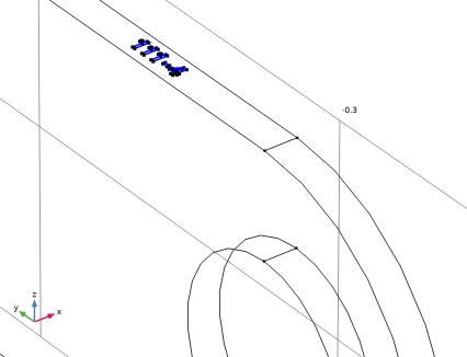
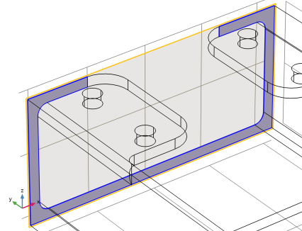
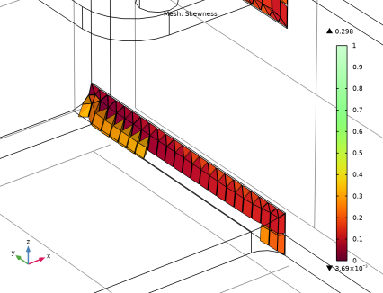
Click the Zoom Box button on the Graphics toolbar and then use the mouse to zoom in to the corner on the bracket displayed below to get a better view of the elements.
8
Click the  Go to Default View button in the Graphics toolbar.
Geometry 1
A better strategy for partitioning would be to create domains that include the fillets together with a small region of the surrounding volume. This will also make it possible to generate a tetrahedral mesh for the region including the fillets, while using swept mesh in the remaining domains. Continue by testing this strategy.
To generate the domains around the fillets, first create solid objects by extruding a 2D drawing. These solid objects will become the tools that you will use to partition the bracket.
Import 1 (imp1)
1
In the Model Builder window, under Component 1 (comp1)>Geometry 1 click Import 1 (imp1).
2
In the Settings window for Import, click  Build Selected.
Work Plane 1 (wp1)
1
In the Geometry toolbar, click  Work Plane.
2
In the Settings window for Work Plane, locate the Plane Definition section.
3
From the Plane type list, choose Face parallel.
4
On the object imp1, select Boundary 7 only.
5
In the Offset in normal direction text field, type 0.02.
Work Plane 1 (wp1)>Plane Geometry
In the Model Builder window, click Plane Geometry.
Work Plane 1 (wp1)>Rectangle 1 (r1)
1
In the Work Plane toolbar, click  Rectangle.
2
In the Settings window for Rectangle, locate the Size and Shape section.
3
In the Width text field, type 0.033.
4
In the Height text field, type 0.024.
5
Locate the Position section. In the xw text field, type -0.06.
6
In the yw text field, type 0.086.
Work Plane 1 (wp1)>Rectangle 2 (r2)
1
Right-click Component 1 (comp1)>Geometry 1>Work Plane 1 (wp1)>Plane Geometry>Rectangle 1 (r1) and choose Duplicate.
2
In the Settings window for Rectangle, locate the Position section.
3
In the xw text field, type 0.027.
4
Click  Build Selected.
Work Plane 1 (wp1)>Rectangle 3 (r3)
1
Right-click Rectangle 1 (r1) and choose Duplicate.
2
In the Settings window for Rectangle, locate the Position section.
3
In the yw text field, type -0.11.
4
Click  Build Selected.
Work Plane 1 (wp1)>Rectangle 4 (r4)
1
Right-click Component 1 (comp1)>Geometry 1>Work Plane 1 (wp1)>Plane Geometry>Rectangle 3 (r3) and choose Duplicate.
2
In the Settings window for Rectangle, locate the Position section.
3
In the xw text field, type 0.027.
4
Click  Build Selected.
Work Plane 1 (wp1)
1
In the Model Builder window, under Component 1 (comp1)>Geometry 1 click Work Plane 1 (wp1).
2
In the Settings window for Work Plane, click  Build Selected.
Extrude 1 (ext1)
1
In the Geometry toolbar, click  Extrude.
2
In the Settings window for Extrude, locate the Distances section.
3
4
Select the Reverse direction check box.
5
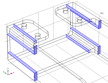
Locate the Selections of Resulting Entities section. Select the Resulting objects selection check box.
This option generates a selection that contains the output objects of the extrude operation. The selection can be used as input to subsequent operations and eliminates the need to select the objects, and its entities, by clicking in the Graphics window.
6
Click  Build All Objects.
Partition Domains 1 (pard1)
Using the extruded solids, you can now partition the bracket using the Partition Domains operation used earlier.
1
In the Model Builder window, click Partition Domains 1 (pard1).
2
In the Settings window for Partition Domains, locate the Partition Domains section.
3
Find the Domains to partition subsection. Click to select the  Activate Selection toggle button.
4
5
From the Partition with list, choose Objects.
6
From the Objects list, choose Extrude 1.
7
Clear the Keep objects check box.
8
Click  Build All Objects.
Mesh Control Faces 1 (mcf1)
While it is advantageous to be able to partition the geometry for meshing, the additional domains often require extra steps during the simulation setup, for example to define material properties. To avoid this, use the Mesh Control Faces feature to remove the interior faces that separate the domains. The faces selected in the mesh control feature will be available for meshing, but removed from the geometry as soon as the adjacent domains are meshed.
1
In the Geometry toolbar, click  Virtual Operations and choose Mesh Control Faces.
2
In the Settings window for Mesh Control Faces, locate the Input section.
3
From the Faces to include list, choose Extrude 1.
The Extrude 1 selection contains the faces that remain in the geometry from the Extrude 1 operation. These faces are the interior faces that separate the domains.
The selected faces will be removed after meshing.
Mesh 1
The geometry is now ready, and you can continue with setting up the mesh. Because you are combining the swept mesh with a tetrahedral mesh, first remove the domains containing the fillets from the Swept 1 operation.
Swept 1
1
In the Model Builder window, under Component 1 (comp1)>Mesh 1 click Swept 1.
2
In the Settings window for Swept, locate the Domain Selection section.
3
From the Geometric entity level list, choose Domain.
4
To lower the number of elements, generate hexahedral elements by meshing the source faces with a quadrilateral mesh.
5
Locate the Sweep Method section. From the Face meshing method list, choose Quadrilateral (generate hexahedra).
6
Click  Build All.
Free Tetrahedral 1
1
In the Mesh toolbar, click  Free Tetrahedral.
2
In the Settings window for Free Tetrahedral, click  Build All.
Although not visible from the surface mesh rendered in the Graphics window, the mesher automatically inserted a layer of pyramid elements between the hexahedral and tetrahedral elements. Further ahead, you will generate a mesh plot to visualize these elements.
By default, the mesher also smoothes the transition in element size across the removed mesh control faces. The effect of the smoothing is detectable by looking at the surface elements at the location of the removed edges of the interior faces.
3
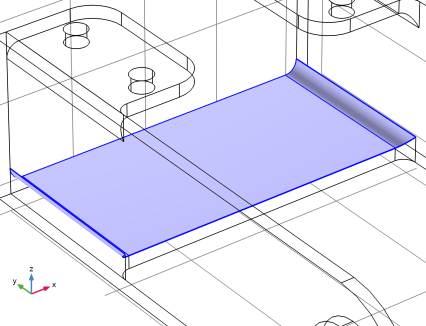
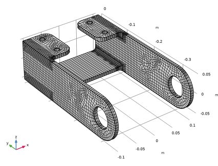
Click the Zoom Box button on the Graphics toolbar and then use the mouse to zoom in to the region below.
In the figure above, where the quadrilateral elements meet the triangular elements, the elements do not follow the straight line of the removed edges. Next, test how to turn off the option to smooth the transition in element size across the removed mesh control faces.
4
In the Model Builder window, click Free Tetrahedral 1.
5
Click to expand the Control Entities section. Clear the Smooth across removed control entities check box.
6
Click  Build Selected.
With the option to smooth the transition in element size across the removed mesh control faces turned off, the interface between the triangular and quadrilateral elements now follows the straight line of the removed edges.
7
Click the  Go to Default View button in the Graphics toolbar.
8
In the Model Builder window, right-click Mesh 1 and choose Statistics.
According to the information in the Statistics window, the minimum element quality of the mesh is now around 0.2, which is considered good for most applications. It is also possible to display information for the individual element types in the mesh.
9
From the Element type list, choose Tetrahedron.
The minimum quality of the tetrahedral elements corresponds to the overall minimum quality of the mesh, that is, the element with the lowest quality is a tetrahedron.
Size 1
Some simulation types require a better resolution of the curved faces of the fillets. For example, when you are interested in accurately determining the stresses in a structural mechanics analysis. You can specify smaller elements for these regions by using a Size attribute for the Free Tetrahedral 1 node.
1
In the Model Builder window, right-click Free Tetrahedral 1 and choose Size.
2
In the Settings window for Size, locate the Element Size section.
3
From the Predefined list, choose Finer.
Free Tetrahedral 1
1
In the Model Builder window, right-click Free Tetrahedral 1 and choose Build All.
In this final mesh, which has approximately 20000 domain elements, the fillet regions are better resolved by the mesh.
2
Right-click Mesh 1 and choose Statistics.
A look in the Statistics window reveals that the minimum element quality is slightly lower than before, but still good enough for most simulations.
Results
In the final steps of this tutorial, modify the mesh plot you created earlier to be able to view how the layer of pyramid elements interfaces the hexahedral elements in the mesh.
Mesh 1
1
In the Model Builder window, under Results>Mesh Plot 1 click Mesh 1.
2
In the Settings window for Mesh, locate the Level section.
3
From the Element type list, choose Pyramid.
4
Locate the Element Filter section. Clear the Enable filter check box.
5
Locate the Coloring and Style section. From the Element color list, choose Magenta.
Filter 1
1
Right-click Mesh 1 and choose Filter.
2
In the Settings window for Filter, locate the Element Selection section.
3
In the Logical expression for inclusion text field, type (x<-0.08)*(z>0.02)*(y>-0.13).
4
In the Mesh Plot 1 toolbar, click  Plot.
Mesh 2
1
Right-click Mesh 1 and choose Duplicate.
2
In the Settings window for Mesh, locate the Level section.
3
From the Element type list, choose Hexahedron.
4
Locate the Coloring and Style section. From the Element color list, choose Gray.
5
In the Mesh Plot 1 toolbar, click  Plot.
6
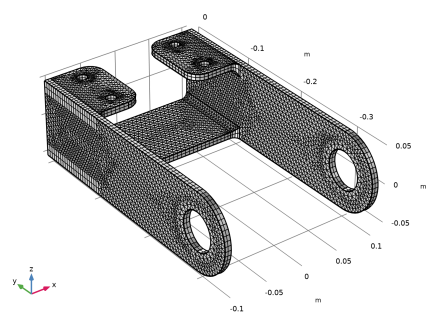
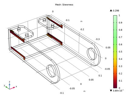
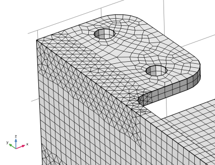
Click the Zoom Box button on the Graphics toolbar and then use the mouse to zoom in to get a better view of the elements.