You are viewing the documentation for an older COMSOL version. The latest version is available here.
PDF

Control of an Inverted Pendulum
Introduction
An inverted pendulum is a pivot-mounted structure for which the position of the center gravity is placed above the pivot point. The structure in its original position is unstable, and without exterior force it will always tend to fall down. This is a classical problem within control systems engineering — keeping the structure in equilibrium by applying an external load on the cart. The control load depends on the pendulum tilting angle, the cart position, and the cart velocity. The equilibrium is assumed when all control parameters are zero.
Note: This models requires licenses for the Structural Mechanics Module and LiveLink™ for Simulink®.
Model Definition
The mechanical model of the pendulum is implemented in COMSOL Multiphysics. The pendulum system consists of a 50 cm x 0.5 cm x 0.5 cm rod and a 2 kg cart. The rod is pivot mounted on the cart, and the last one is free to move horizontally. In COMSOL Multiphysics, the rod is modeled using a 2D geometry and as a rigid domain, while the cart is only represented with its mass.
The control system is implemented in Simulink using three PID controllers that provide the force to apply to the cart in order to hold the pendulum in balance. The rod is considered in equilibrium when the tilting angle, the cart position, and the cart velocity are zero. These are the values returned by the COMSOL simulation used by the PID controllers.
The cosimulation with COMSOL Multiphysics and Simulink is set up by exporting a COMSOL Cosimulation file from the COMSOL model and then adding this file to the COMSOL Cosimulation block in the Simulink simulation diagram. The input of the block consists of perturbation and control forces provided by Simulink. The block has three outputs: the tilting rotation of the rod, the displacement, and the velocity of the cart.
The rod is dropped with an initial tilting angle of 1 degree, and a perturbation force is applied as a 0.2 s pulse with a 0.2 N amplitude.
Figure 1 shows the full control simulation diagram in Simulink.
Figure 1: Simulink diagram of the inverted pendulum cosimulation.
The simulation diagram is made so that you can modify the perturbation force or set a different initial tilting angle.
Results and Discussion
Figure 2 shows the tilting of the pendulum. After the perturbation with a maximum angle of around 18 degrees, the pendulum is stabilized around a vertical position.
Figure 2: Tilting angle of the pendulum versus time.
Figure 3 shows the chart displacement, which never exceeds 0.4 m and gets stabilized at the original position.
Figure 3: Chart displacement versus time.
Figure 4 shows the translational velocity of the pendulum that quickly decreases and approaches 0.
Figure 4: Chart velocity versus time.
Figure 5 shows the input force. Just after the perturbation, the control force is quickly adjusted. After 1 s, the force varies smoothly until the pendulum is fully stabilized.
Figure 5: Control force applied on the chart along the time.
Setting Up the Cosimulation
Follow the workflow below to set up the cosimulation with COMSOL Multiphysics and Simulink:
1
2
3
4
5
6
Application Library path: LiveLink_for_Simulink/Tutorials/inverted_pendulum
Modeling Instructions — COMSOL Desktop
From the File menu, choose New.
New
In the New window, click  Model Wizard.
Model Wizard
1
In the Model Wizard window, click  2D.
2
In the Select Physics tree, select Structural Mechanics>Solid Mechanics (solid).
3
Click Add.
4
Click  Study.
5
In the Select Study tree, select General Studies>Time Dependent.
6
Global Definitions
Parameters 1
1
In the Model Builder window, under Global Definitions click Parameters 1.
2
In the Settings window for Parameters, locate the Parameters section.
3
Geometry 1
1
In the Model Builder window, under Component 1 (comp1) click Geometry 1.
2
In the Settings window for Geometry, locate the Units section.
3
From the Angular unit list, choose Radians.
Rectangle 1 (r1)
1
In the Geometry toolbar, click  Rectangle.
2
In the Settings window for Rectangle, locate the Size and Shape section.
3
In the Width text field, type w0.
4
In the Height text field, type l0.
5
Locate the Position section. In the x text field, type -w0/2.
Point 1 (pt1)
1
In the Geometry toolbar, click  Point.
2
In the Settings window for Point, locate the Point section.
3
In the x text field, type 0 0.
4
In the y text field, type 0 l0.
Rotate 1 (rot1)
1
In the Geometry toolbar, click  Transforms and choose Rotate.
2
Click in the Graphics window and then press Ctrl+A to select all objects.
3
In the Settings window for Rotate, locate the Rotation section.
4
In the Angle text field, type alpha0.
Add Material
1
In the Home toolbar, click  Add Material to open the Add Material window.
2
Go to the Add Material window.
3
In the tree, select Built-in>Structural steel.
4
Click Add to Component in the window toolbar.
5
In the Home toolbar, click  Add Material to close the Add Material window.
Solid Mechanics (solid)
1
In the Model Builder window, under Component 1 (comp1) click Solid Mechanics (solid).
2
In the Settings window for Solid Mechanics, locate the Thickness section.
3
In the d text field, type w0.
Rigid Material 1
1
In the Physics toolbar, click  Domains and choose Rigid Material.
2
3
In the Settings window for Rigid Material, locate the Center of Rotation section.
4
From the list, choose Centroid of selected entities.
5
From the Entity level list, choose Point.
Center of Rotation: Point 1
1
In the Model Builder window, click Center of Rotation: Point 1.
2
Rigid Material 1
In the Model Builder window, click Rigid Material 1.
Prescribed Displacement/Rotation 1
1
In the Physics toolbar, click  Attributes and choose Prescribed Displacement/Rotation.
2
In the Settings window for Prescribed Displacement/Rotation, locate the Prescribed Displacement at Center of Rotation section.
3
Select the Prescribed in y direction check box.
Rigid Material 1
In the Model Builder window, click Rigid Material 1.
Applied Force 1
1
In the Physics toolbar, click  Attributes and choose Applied Force.
2
In the Settings window for Applied Force, locate the Applied Force section.
3
Specify the F vector as
Rigid Material 1
In the Model Builder window, click Rigid Material 1.
Mass and Moment of Inertia 1
1
In the Physics toolbar, click  Attributes and choose Mass and Moment of Inertia.
2
In the Settings window for Mass and Moment of Inertia, locate the Mass and Moment of Inertia section.
3
In the m text field, type M.
Gravity 1
In the Physics toolbar, click  Global and choose Gravity.
Point Load 1
1
In the Physics toolbar, click  Points and choose Point Load.
2
3
In the Settings window for Point Load, locate the Force section.
4
Specify the FP vector as
Mesh 1
Mapped 1
1
In the Mesh toolbar, click  Mapped.
2
Click  Build Mesh.
Definitions
To define the cosimulation block output you need to create first global variable probes.
Global Variable Probe 1 (var1)
1
In the Model Builder window, under Component 1 (comp1) right-click Definitions and choose Global Variable Probe.
2
In the Settings window for Global Variable Probe, type rot in the Variable name text field.
3
Locate the Expression section. In the Expression text field, type solid.rd1.phi+alpha0.
Global Variable Probe 2 (var2)
1
In the Model Builder window, right-click Definitions and choose Global Variable Probe.
2
In the Settings window for Global Variable Probe, locate the Expression section.
3
In the Expression text field, type solid.rd1.u.
4
In the Variable name text field, type disp.
Global Variable Probe 3 (var3)
1
Right-click Definitions and choose Global Variable Probe.
2
In the Settings window for Global Variable Probe, type vel in the Variable name text field.
3
Locate the Expression section. In the Expression text field, type solid.rd1.u_tx.
Study 1
Step 1: Time Dependent
1
In the Model Builder window, under Study 1 click Step 1: Time Dependent.
2
In the Settings window for Time Dependent, locate the Study Settings section.
3
In the Output times text field, type range(0,1e-2,2).
4
Select the Include geometric nonlinearity check box.
Solution 1 (sol1)
1
In the Study toolbar, click  Show Default Solver.
2
In the Model Builder window, expand the Solution 1 (sol1) node.
3
In the Model Builder window, expand the Study 1>Solver Configurations>Solution 1 (sol1)>Time-Dependent Solver 1 node, then click Fully Coupled 1.
4
In the Settings window for Fully Coupled, click to expand the Method and Termination section.
5
From the Nonlinear method list, choose Automatic (Newton).
6
Click  Compute.
Results
Surface 1
1
In the Model Builder window, expand the Stress (solid) node, then click Surface 1.
2
In the Settings window for Surface, locate the Expression section.
3
In the Expression text field, type 1.
4
Locate the Coloring and Style section. From the Coloring list, choose Uniform.
5
From the Color list, choose Gray.
Stress (solid)
In the Model Builder window, expand the Surface 1 node, then click Results>Stress (solid).
Point Trajectories 1
1
In the Stress (solid) toolbar, click  More Plots and choose Point Trajectories.
2
In the Settings window for Point Trajectories, locate the Trajectory Data section.
3
From the Plot data list, choose Points.
4
In the X-expression text field, type x.
5
In the Y-expression text field, type y.
6
7
Locate the Coloring and Style section. Find the Point style subsection. From the Type list, choose Point.
8
In the Point radius expression text field, type 0.005.
Animation 1
1
In the Stress (solid) toolbar, click  Animation and choose Player.
2
In the Settings window for Animation, locate the Frames section.
3
In the Number of frames text field, type 250.
Save the COMSOL Model
1
From the File menu, choose Save As.
2
Browse to a suitable folder, enter the filename inverted_pendulum.mph, and then click Save.
Exporting the Cosimulation File
In the following configure the cosimulation, and export the file for cosimulation that will be loaded into Simulink.
Global Definitions
Cosimulation for Simulink 1
1
In the Study toolbar, click  Cosimulation for Simulink.
2
In the Settings window for Cosimulation for Simulink, locate the Filename section.
3
In the Filename text field, type inverted_pendulum.
4
Locate the Inputs section. Click  Add.
5
6
7
8
Click to expand the Block Parameters section. Click  Add.
9
10
Locate the Outputs section. In the table, enter the following settings:
11
Click  Export.
Modeling Instructions — Simulink
Once you have created the COMSOL model and saved the cosimulation file you can start Simulink to continue with the setup there.
1
2
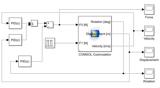
In MATLAB enter the command mphapplicationlibraries to start the GUI for viewing models from the LiveLink for Simulink application library.
3
4
The included COMSOL Cosimulation block is already configured with a cosimulation file based on the model from the COMSOL Application Library and ready to run. If you want to run the simulation directly, go to Step 7 below. Else, if you want to use the model file and cosimulation file you have created by following the steps in the section Modeling Instructions — COMSOL Desktop, you can continue with Step 5 below.
5
6
Note: In case the folder path of the file for cosimulation for Simulink is not set in MATLAB enter the full filename.
For this simulation the stop time is set to 10 s and the communication step size is set to 0.02 s.
7
8
Postprocessing the Solution in the COMSOL Desktop
Once you have run the simulation in Simulink you can postprocess the computed solution stored in the COMSOL model, for instance the steps below show how to generate an animation of the pendulum.
1
mphlaunch
This will start a COMSOL Desktop with the model used to run the cosimulation.
2
In the Model Builder, expand the Results node, and then expand the Export node.
3
Select the Animation 1 node, and click Show Frame.
Note: Close the COMSOL Desktop before running a new simulation in Simulink.