|
|
|
|
•
|
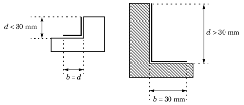
unventilated cavities, completely closed or connected either to the exterior or to the interior by a slit with a width not exceeding 2 mm
|
|
•
|
slightly ventilated cavities, connected either to the exterior or to the interior by a slit greater than 2 mm but not exceeding 10 mm
|
|
•
|
well-ventilated cavities, corresponding to a configuration not covered by one of the two preceding types
|

|
•
|
|
•
|
|
•
|
ΔT is the maximum surface temperature difference in the cavity
|
|
•
|
|
•
|
Tm is the average temperature on the boundaries of the cavity
|
|
•
|
E is the intersurface emittance, defined by:
|

|
•
|
|
•
|
F is the view factor of the rectangular section, defined by:
|

|
•
|
d is the cavity dimension in the heat flow rate direction
|
|
•
|
b is the cavity dimension perpendicular to the heat flow rate direction
|

|
•
|
|
•
|
|
L2D (W/(m·K))
|
|||
|
L2D (W/(m·K))
|
|||
|
L2D (W/(m·K))
|
|||
|
L2D (W/(m·K))
|
|||
|
L2D (W/(m·K))
|
|||
|
L2D (W/(m·K))
|
|||
|
1
|
|
2
|
In the Application Libraries window, select Heat Transfer Module>Buildings and Constructions>windows_thermal_performances_preset in the tree.
|
|
3
|
Click
|
|
1
|
In the Model Builder window, expand the First Window (comp1)>Definitions node, then click Variables 1.
|
|
2
|
|
4
|
|
1
|
In the Model Builder window, expand the Heat Transfer in Solids and Fluids (ht) node, then click Fluid 1.
|
|
1
|
|
2
|
|
3
|
|
4
|
|
5
|
|
6
|
|
1
|
|
2
|
|
3
|
|
4
|
|
5
|
|
6
|
|
1
|
|
2
|
|
3
|
|
4
|
|
5
|
|
6
|
|
7
|
|
1
|
|
1
|
|
2
|
|
3
|
In the Settings window for Global Evaluation, type Thermal Conductance of the Section (L2D) 1 in the Label text field.
|
|
4
|
Locate the Expressions section. In the table, enter the following settings:
|
|
5
|
Click
|
|
1
|
Go to the Table window.
|
|
1
|
|
2
|
|
3
|
|
4
|
|
1
|
In the Model Builder window, expand the Second Window (comp2)>Definitions node, then click Variables 2.
|
|
2
|
|
4
|
|
1
|
In the Model Builder window, expand the Heat Transfer in Solids and Fluids 2 (ht2) node, then click Fluid 1.
|
|
1
|
|
2
|
|
3
|
|
4
|
|
5
|
|
6
|
|
1
|
|
2
|
|
3
|
|
4
|
|
5
|
|
6
|
|
1
|
|
2
|
|
3
|
|
4
|
|
5
|
|
6
|
|
7
|
|
1
|
|
2
|
In the Settings window for Global Evaluation, type Thermal Conductance of the Section (L2D) 2 in the Label text field.
|
|
3
|
|
4
|
Locate the Expressions section. In the table, enter the following settings:
|
|
5
|
Click
|
|
1
|
Go to the Table window.
|
|
1
|
|
2
|
|
3
|
|
4
|
|
1
|
In the Model Builder window, expand the Third Window (comp3)>Definitions node, then click Variables 3.
|
|
2
|
|
4
|
|
1
|
In the Model Builder window, expand the Heat Transfer in Solids and Fluids 3 (ht3) node, then click Fluid 1.
|
|
1
|
|
2
|
|
3
|
|
4
|
|
5
|
|
6
|
|
1
|
|
2
|
|
3
|
|
4
|
|
5
|
|
6
|
|
1
|
|
2
|
|
3
|
|
4
|
|
5
|
|
6
|
|
7
|
|
1
|
In the Model Builder window, under Third Window (comp3) right-click Mesh 3 and choose Edit Physics-Induced Sequence.
|
|
2
|
|
3
|
|
4
|
|
1
|
|
2
|
In the Settings window for Global Evaluation, type Thermal Conductance of the Section (L2D) 3 in the Label text field.
|
|
3
|
|
4
|
Locate the Expressions section. In the table, enter the following settings:
|
|
5
|
Click
|
|
1
|
Go to the Table window.
|
|
1
|
|
2
|
|
3
|
|
4
|
|
1
|
In the Model Builder window, expand the Fourth Window (comp4)>Definitions node, then click Variables 4.
|
|
2
|
|
4
|
|
1
|
In the Model Builder window, under Fourth Window (comp4) click Heat Transfer in Solids and Fluids 4 (ht4).
|
|
2
|
In the Settings window for Heat Transfer in Solids and Fluids, click to expand the Discretization section.
|
|
3
|
|
1
|
In the Model Builder window, expand the Heat Transfer in Solids and Fluids 4 (ht4) node, then click Fluid 1.
|
|
1
|
|
2
|
|
3
|
|
4
|
|
5
|
|
6
|
|
1
|
|
2
|
|
3
|
|
4
|
|
5
|
|
6
|
|
1
|
|
2
|
|
3
|
|
4
|
|
5
|
|
6
|
|
7
|
|
1
|
In the Model Builder window, under Fourth Window (comp4) right-click Mesh 4 and choose Edit Physics-Induced Sequence.
|
|
2
|
|
3
|
|
4
|
|
1
|
|
2
|
In the Settings window for Global Evaluation, type Thermal Conductance of the Section (L2D) 4 in the Label text field.
|
|
3
|
|
4
|
Locate the Expressions section. In the table, enter the following settings:
|
|
5
|
Click
|
|
1
|
Go to the Table window.
|
|
1
|
|
2
|
|
3
|
|
4
|
|
1
|
In the Model Builder window, expand the Fifth Window (comp5)>Definitions node, then click Variables 5.
|
|
2
|
|
4
|
|
1
|
In the Model Builder window, expand the Heat Transfer in Solids and Fluids 5 (ht5) node, then click Fluid 1.
|
|
1
|
|
2
|
|
3
|
|
4
|
|
5
|
|
6
|
|
1
|
|
2
|
|
3
|
|
4
|
|
5
|
|
6
|
|
1
|
|
2
|
|
3
|
|
4
|
|
5
|
|
6
|
|
7
|
|
1
|
|
2
|
In the Settings window for Global Evaluation, type Thermal Conductance of the Section (L2D) 5 in the Label text field.
|
|
3
|
|
4
|
Locate the Expressions section. In the table, enter the following settings:
|
|
5
|
Click
|
|
1
|
Go to the Table window.
|
|
1
|
|
2
|
|
3
|
|
4
|
|
1
|
In the Model Builder window, expand the Sixth Window (comp6)>Definitions node, then click Variables 6.
|
|
2
|
|
4
|
|
1
|
In the Model Builder window, expand the Heat Transfer in Solids and Fluids 6 (ht6) node, then click Fluid 1.
|
|
1
|
|
2
|
|
3
|
|
4
|
|
5
|
|
6
|
|
1
|
|
2
|
|
3
|
|
4
|
|
5
|
|
6
|
|
1
|
|
2
|
|
3
|
|
4
|
|
5
|
|
6
|
|
7
|
|
1
|
|
2
|
In the Settings window for Global Evaluation, type Thermal Conductance of the Section (L2D) 6 in the Label text field.
|
|
3
|
|
4
|
Locate the Expressions section. In the table, enter the following settings:
|
|
5
|
Click
|
|
1
|
Go to the Table window.
|
|
1
|
|
2
|
|
3
|
|
4
|