PDF

Brittle Fracture of a Holed Plate
Introduction
This example studies the brittle fracture of a holed plate made of a cement mortar. The set up of the model, including dimensions and material properties, is based on the experimental data reported in Ref. 1. As the plate is loaded, a mixed-mode fracture is induced with a crack propagating from the predefined notch to the unsymmetrically placed hole in the center of the plate.
Fracture is modeled using a damage model that regularizes the sharp geometry of the crack by the phase field approximation. This means that the crack is described in the domain material, so the non local phase field makes the crack path independent of the mesh elements. The example shows how to define an efficient and stable solver configuration for the phase field damage method, which is often unstable for this class of problems.
Model Definition
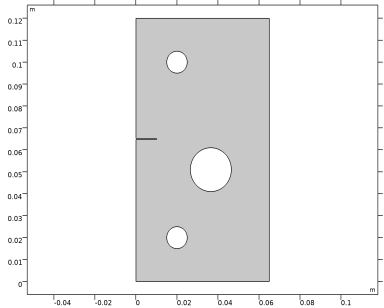
The geometry of the specimen (Ref. 1) is shown in Figure 1. The overall dimensions of the plate equal to 65 mm in width and 120 mm in height. The thickness of the plate is constant and equal to 1 mm. A notch is placed on the left boundary, 65 mm from the bottom of the plate, in order to control where the crack initiates during loading. A mixed-mode fracture is induced by offsetting the large hole and the notch from the center of the plate. Loading is applied through displacement controlled metal pins inserted into the two smaller holes. The model assumes a plane stress condition.
Figure 1: Geometry of the holed plate model.
The plate is made of a cement mortar composed of 22% cement, 66% sand with a grain size smaller than 1 mm, and 12% water. Material properties (from Ref. 1) are given in Table 1. In order to account for tensile cracking, the mortar is described as a linear elastic material model with damage. A phase field approximation is made after the sharp crack geometry, and cracking is incorporated in to the domain material. The set up of the phase field damage model does not include a damage threshold, meaning that all material points subjected to tension are damaged. The only material input to the damage model is the critical energy release rate Gc (sometimes called fracture energy), whereas the tensile strength is determined by the damage evolution function and the evolution of the phase field. The latter can be modified by the internal length scale lint that controls the width of the localized phase field. In this example, the parameter lint is set to 0.25 mm.
To properly resolve the phase field and to achieve a stable material behavior, a high mesh density is required in the vicinity of the propagating crack. Since the expected crack trajectory is known in advance, the mesh is locally refined with a maximum mesh element size equal to lint. This length can be considered as being close to the upper limit of the appropriate mesh size. If extra computational cost is acceptable, a finer mesh size would resolve the phase field better and also yield a more stable material behavior.
The two metal pins in the model are represented by two rigid connectors attached to the boundaries of the two smaller holes. Loading is applied by prescribed displacements to the two rigid connectors while they are free to rotate. No other loads nor constraints are considered.
Results and Discussion
Figure 2 shows the reaction force in the upper rigid connector versus its prescribed displacement. A first peak in the curve can be identified at a load of 0.63 kN and a lateral displacement of 0.33 mm. As shown in Figure 3, this peak corresponds to the formation of a crack a the tip of the notch. Actually, the crack starts propagating slightly before the observed peak, see the first green circle in Figure 2 and leftmost plot in Figure 3. Once in the post-peak regime of the curve, the crack propagates rapidly and the load capacity of the plate reduces significantly. As the crack approaches the large hole, its diverts from the initially straight path; and a new stable configuration is obtained once it reaches the hole. At this point the load can be increased, but with a much lower stiffness than prior to the formation of the crack.
A second peak is reached at a load of 0.15 kN and 1.7 mm displacement. A second crack propagates toward the right boundary of the plate, and it would eventually split the specimen in two pieces. However, due to local compressive stress fields and residual stiffness in the damaged mesh elements in the model, the crack propagation is slowed down before reaching the exterior boundary. By increasing the prescribed displacement of the rigid connector; the crack would eventually reach the exterior also in the simulation when the bending action of the plate changes to pure tensile loading.
The distribution of the phase field at the last step of the simulation is shown in Figure 4. The phase field has a smooth variation, which indicates that the mesh resolution is sufficiently fine. For the second crack, the phase field is slightly wider close the hole, since there it localized without the aid of a geometric notch. Localization of strains is an unstable event, which explains the small bleeding of the phase field observed in the second crack.
Figure 2: Load versus displacement curve with green circles indicating the snapshots presented in Figure 3.
Figure 3: Crack trajectory and maximum principal stress field for different parameter steps. The red arrows indicate the relative size of the reaction force in the rigid connectors.
Figure 4: Crack phase field at the last parameter step.
Notes About the COMSOL Implementation
The loading of the specimen is done by adding a Prescribed Displacement node to each Rigid Connector. In this way the loading is displacement-controlled, which is necessary to track the peak loads in the global response. The simulation would have stopped before reaching the first peak if used a load-controlled set up.
While it is possible to solve this type of brittle fracture problem using a fully coupled strategy, the phase field damage model can often exhibit poor or slow convergence. In this example it is therefore shown how to use a segregated strategy to improve the convergence and stability of the numerical solution by splitting the evolution of the crack phase field and the displacement field into two groups. This type of algorithmic operator split for phase field fracture models was originally suggested in Ref. 2, and it can conceptually be summarized as follows for step n + 1:
1
Initialization. At step n, the crack phase field, the displacement field, and other state variables are known.
2
Update state variables. Update internal state variables with the values from step n.
3
Solve for the Crack Phase Field. Compute the crack phase field variable in a Newton step, with the displacement field frozen at step n.
4
Solve for the Displacement field. Compute the displacement field variable in a Newton step with the updated crack phase field.
These steps lead to a single-pass algorithm which corresponds to the default solver sequence that is, however, accurate only for sufficiently small parameter steps. An improvement to this scheme is to add a multi-pass correction, by iterating in each increment over steps 3 and 4 until either convergence is achieved or for a predefined number of iterations. Such a strategy is used in this example by setting the Number of iteration to 3 in the Segregated subnode under the Stationary Solver.
Notice that the suggested solver configuration does not require convergence of the outer problem, and the solution is always accepted after 3 segregated iterations. However, each sub group locally fulfills the defined convergence criteria. Hence, the displacement field can be considered as a converged solution given the current crack phase field.
The accuracy of the scheme can be improved if the extra computational cost of increasing the number of iterations (or the required convergence of the outer problem) is acceptable.
References
1. M. Ambati, T. Gerasimov, and L. De Lorenzis, “A review on phase-field models of brittle fracture and a new fast hybrid formulation,” Comput. Mech., vol. 55, pp. 383–405, 2015.
2. C. Miehe, M. Hofhacker, and F. Welschinger, “A phase field model for rate-independent crack propagation: Robust algorithmic implementation based on operator splits,” Comput. Methods Appl. Mech. Eng., vol. 199, pp. 2765–2778, 2010.
Application Library path: Geomechanics_Module/Damage/holed_plate_fracture
Modeling Instructions
From the File menu, choose New.
New
In the New window, click  Model Wizard.
Model Wizard
1
In the Model Wizard window, click  2D.
2
In the Select Physics tree, select Structural Mechanics>Solid Mechanics (solid).
3
Click Add.
4
Click  Study.
5
In the Select Study tree, select General Studies>Stationary.
6
Global Definitions
Parameters 1
1
In the Model Builder window, under Global Definitions click Parameters 1.
2
In the Settings window for Parameters, locate the Parameters section.
3
Geometry 1
Rectangle 1 (r1)
1
In the Geometry toolbar, click  Rectangle.
2
In the Settings window for Rectangle, locate the Size and Shape section.
3
In the Width text field, type width.
4
In the Height text field, type height.
Circle 1 (c1)
1
In the Geometry toolbar, click  Circle.
2
In the Settings window for Circle, locate the Size and Shape section.
3
In the Radius text field, type holeRadius.
4
Locate the Position section. In the x text field, type holeX.
5
In the y text field, type holeY.
Circle 2 (c2)
1
In the Geometry toolbar, click  Circle.
2
In the Settings window for Circle, locate the Size and Shape section.
3
In the Radius text field, type 5[mm].
4
Locate the Position section. In the x text field, type 20[mm].
5
In the y text field, type 20[mm].
Circle 3 (c3)
1
In the Geometry toolbar, click  Circle.
2
In the Settings window for Circle, locate the Size and Shape section.
3
In the Radius text field, type 5[mm].
4
Locate the Position section. In the x text field, type 20[mm].
5
In the y text field, type height-20[mm].
Rectangle 2 (r2)
1
In the Geometry toolbar, click  Rectangle.
2
In the Settings window for Rectangle, locate the Size and Shape section.
3
In the Width text field, type notchWidth.
4
In the Height text field, type notchHeight.
5
Locate the Position section. In the y text field, type notchLocation-notchHeight/2.
Difference 1 (dif1)
1
In the Geometry toolbar, click  Booleans and Partitions and choose Difference.
2
Drag and drop below Rectangle 2 (r2).
3
4
In the Settings window for Difference, locate the Difference section.
5
Find the Objects to subtract subsection. Click to select the  Activate Selection toggle button.
6
Select the objects c1, c2, c3, and r2 only.
Partition the plate to facilitate an increased mesh density around the expected crack path.
Line Segment 1 (ls1)
1
In the Geometry toolbar, click  More Primitives and choose Line Segment.
2
In the Settings window for Line Segment, locate the Starting Point section.
3
From the Specify list, choose Coordinates.
4
In the x text field, type width.
5
In the y text field, type holeY+elemSize*12.
6
Locate the Endpoint section. From the Specify list, choose Coordinates.
7
In the x text field, type holeX.
8
In the y text field, type holeY+elemSize*5.
Line Segment 2 (ls2)
1
Right-click Line Segment 1 (ls1) and choose Duplicate.
2
In the Settings window for Line Segment, locate the Starting Point section.
3
In the y text field, type holeY-elemSize*12.
4
Locate the Endpoint section. In the y text field, type holeY-elemSize*5.
Polygon 1 (pol1)
1
In the Geometry toolbar, click  Polygon.
2
In the Settings window for Polygon, locate the Object Type section.
3
From the Type list, choose Open curve.
4
Locate the Coordinates section. In the table, enter the following settings:
Polygon 2 (pol2)
1
In the Geometry toolbar, click  Polygon.
2
In the Settings window for Polygon, locate the Object Type section.
3
From the Type list, choose Open curve.
4
Locate the Coordinates section. In the table, enter the following settings:
Union 1 (uni1)
1
In the Geometry toolbar, click  Booleans and Partitions and choose Union.
2
Click the  Select All button in the Graphics toolbar.
Delete Entities 1 (del1)
1
In the Model Builder window, right-click Geometry 1 and choose Delete Entities.
2
On the object uni1, select Boundaries 14–20, 22, and 23 only.
Mesh Control Domains 1 (mcd1)
1
In the Geometry toolbar, click  Virtual Operations and choose Mesh Control Domains.
2
On the object fin, select Domains 3 and 4 only.
3
In the Geometry toolbar, click  Build All.
4
Click the  Zoom Extents button in the Graphics toolbar.
Solid Mechanics (solid)
1
In the Model Builder window, under Component 1 (comp1) click Solid Mechanics (solid).
2
In the Settings window for Solid Mechanics, locate the 2D Approximation section.
3
4
Locate the Thickness section. In the d text field, type 1[mm].
Linear Elastic Material 1
In the Model Builder window, under Component 1 (comp1)>Solid Mechanics (solid) click Linear Elastic Material 1.
Damage 1
1
In the Physics toolbar, click  Attributes and choose Damage.
2
In the Settings window for Damage, locate the Damage section.
3
From the Damage model list, choose Phase field damage.
4
In the lint text field, type 0.25[mm].
Rigid Connector 1
1
In the Physics toolbar, click  Boundaries and choose Rigid Connector.
2
3
In the Settings window for Rigid Connector, locate the Prescribed Displacement at Center of Rotation section.
4
Select the Prescribed in x direction check box.
5
Select the Prescribed in y direction check box.
6
Click to expand the Reaction Force Settings section. Select the Evaluate reaction forces check box.
Rigid Connector 2
1
Right-click Rigid Connector 1 and choose Duplicate.
2
In the Settings window for Rigid Connector, locate the Boundary Selection section.
3
Click  Clear Selection.
4
5
Locate the Prescribed Displacement at Center of Rotation section. In the u0y text field, type para*2[mm].
Materials
Material 1 (mat1)
1
In the Model Builder window, under Component 1 (comp1) right-click Materials and choose Blank Material.
2
In the Settings window for Material, locate the Material Contents section.
3
Mesh 1
Free Quad 1
In the Mesh toolbar, click  Free Quad.
Size 1
1
Right-click Free Quad 1 and choose Size.
2
In the Settings window for Size, locate the Geometric Entity Selection section.
3
From the Geometric entity level list, choose Domain.
4
5
Click to expand the Element Size Parameters section. Locate the Element Size section. Click the Custom button.
6
Locate the Element Size Parameters section.
7
Select the Maximum element size check box. In the associated text field, type elemSize.
Size
1
In the Model Builder window, under Component 1 (comp1)>Mesh 1 click Size.
2
In the Settings window for Size, click to expand the Element Size Parameters section.
3
In the Maximum element size text field, type 0.0075.
4
In the Maximum element growth rate text field, type 2.
5
Click  Build All.
Study 1
Step 1: Stationary
1
In the Model Builder window, under Study 1 click Step 1: Stationary.
2
In the Settings window for Stationary, click to expand the Study Extensions section.
3
Select the Auxiliary sweep check box.
4
5
Solution 1 (sol1)
1
In the Study toolbar, click  Show Default Solver.
2
In the Model Builder window, expand the Solution 1 (sol1) node.
Use a small parameter step to improve the accuracy and stability of the model.
3
In the Model Builder window, expand the Study 1>Solver Configurations>Solution 1 (sol1)>Stationary Solver 1 node, then click Parametric 1.
4
In the Settings window for Parametric, click to expand the Continuation section.
5
Select the Tuning of step size check box.
6
In the Maximum step size text field, type 0.0025.
7
In the Initial step size text field, type 0.0025.
Allowing more outer iterations improves the accuracy of the phase field, but comes at an additional computational cost.
8
In the Model Builder window, under Study 1>Solver Configurations>Solution 1 (sol1)>Stationary Solver 1 click Segregated 1.
9
In the Settings window for Segregated, locate the General section.
10
In the Number of iterations text field, type 3.
Generate datasets and default plots.
11
In the Study toolbar, click  Get Initial Value.
Results
Stress (solid)
1
In the Settings window for 2D Plot Group, locate the Plot Settings section.
2
Clear the Plot dataset edges check box.
Surface 1
1
In the Model Builder window, expand the Stress (solid) node, then click Surface 1.
2
In the Settings window for Surface, locate the Expression section.
3
In the Expression text field, type solid.sdp1Gp.
4
From the Unit list, choose MPa.
Deformation
1
In the Model Builder window, expand the Surface 1 node, then click Deformation.
2
In the Settings window for Deformation, locate the Scale section.
3
Select the Scale factor check box. In the associated text field, type 1.
Line 1
1
In the Model Builder window, right-click Stress (solid) and choose Line.
2
In the Settings window for Line, locate the Expression section.
3
In the Expression text field, type 1.
4
Locate the Coloring and Style section. From the Coloring list, choose Uniform.
5
From the Color list, choose Black.
6
Click to expand the Inherit Style section. From the Plot list, choose Surface 1.
7
Clear the Color check box.
8
Clear the Color and data range check box.
Deformation 1
Right-click Line 1 and choose Deformation.
Study 1
Step 1: Stationary
1
In the Settings window for Stationary, click to expand the Results While Solving section.
2
Select the Plot check box.
3
From the Update at list, choose Steps taken by solver.
4
In the Study toolbar, click  Compute.
Results
Crack Phase Field
1
In the Home toolbar, click  Add Plot Group and choose 2D Plot Group.
2
In the Settings window for 2D Plot Group, type Crack Phase Field in the Label text field.
3
Click to expand the Title section. From the Title type list, choose Label.
4
Locate the Plot Settings section. Clear the Plot dataset edges check box.
Surface 1
1
Right-click Crack Phase Field and choose Surface.
2
In the Settings window for Surface, locate the Expression section.
3
In the Expression text field, type solid.phic.
4
Locate the Coloring and Style section. Click  Change Color Table.
5
In the Color Table dialog box, select Rainbow>RainbowLight in the tree.
6
Crack Trajectory
1
In the Home toolbar, click  Add Plot Group and choose 2D Plot Group.
2
In the Settings window for 2D Plot Group, type Crack Trajectory in the Label text field.
3
Locate the Title section. From the Title type list, choose Label.
4
Locate the Plot Settings section. Clear the Plot dataset edges check box.
5
Locate the Color Legend section. Select the Show units check box.
Surface 1
1
Right-click Crack Trajectory and choose Surface.
2
In the Settings window for Surface, locate the Expression section.
3
In the Expression text field, type 1.
4
Locate the Coloring and Style section. From the Coloring list, choose Uniform.
5
From the Color list, choose Gray.
Deformation 1
1
Right-click Surface 1 and choose Deformation.
2
In the Settings window for Deformation, locate the Scale section.
3
Select the Scale factor check box. In the associated text field, type 1.
Filter 1
1
In the Model Builder window, right-click Surface 1 and choose Filter.
2
In the Settings window for Filter, locate the Element Selection section.
3
In the Logical expression for inclusion text field, type solid.phic<0.6.
Line 1
1
In the Model Builder window, right-click Crack Trajectory and choose Line.
2
In the Settings window for Line, locate the Expression section.
3
In the Expression text field, type 1.
4
Locate the Coloring and Style section. From the Coloring list, choose Uniform.
5
From the Color list, choose Black.
6
Click to expand the Inherit Style section. From the Plot list, choose Surface 1.
7
Clear the Color check box.
8
Clear the Color and data range check box.
Deformation 1
Right-click Line 1 and choose Deformation.
Filter 1
1
In the Model Builder window, right-click Line 1 and choose Filter.
2
In the Settings window for Filter, locate the Element Selection section.
3
In the Logical expression for inclusion text field, type solid.phic<0.6.
Contour 1
1
In the Model Builder window, right-click Crack Trajectory and choose Contour.
2
In the Settings window for Contour, locate the Expression section.
3
In the Expression text field, type solid.sdp1Gp.
4
From the Unit list, choose MPa.
5
Locate the Levels section. From the Entry method list, choose Levels.
6
In the Levels text field, type range(30,10,80).
7
Click to expand the Inherit Style section. From the Plot list, choose Surface 1.
8
Clear the Color check box.
9
Clear the Color and data range check box.
Deformation 1
Right-click Contour 1 and choose Deformation.
Filter 1
1
In the Model Builder window, right-click Contour 1 and choose Filter.
2
In the Settings window for Filter, locate the Element Selection section.
3
In the Logical expression for inclusion text field, type solid.phic<0.9.
4
From the Element nodes to fulfill expression list, choose All.
Crack Trajectory
In the Model Builder window, under Results click Crack Trajectory.
Point Trajectories 1
1
In the Crack Trajectory toolbar, click  More Plots and choose Point Trajectories.
2
In the Settings window for Point Trajectories, click Replace Expression in the upper-right corner of the Trajectory Data section. From the menu, choose Component 1 (comp1)>Solid Mechanics>Rigid connectors>Rigid Connector 1>solid.xcx_rig1,solid.xcy_rig1 - Global coordinates of center of rotation (spatial frame).
3
Locate the Coloring and Style section. Find the Line style subsection. From the Type list, choose None.
4
Find the Point style subsection. From the Type list, choose Arrow.
5
Click thebutton. From the menu, choose Component 1 (comp1)>Solid Mechanics>Rigid connectors>Rigid Connector 1>solid.rig1.RFx,solid.rig1.RFy - Reaction force (spatial frame).
6
Select the Scale factor check box. In the associated text field, type 4E-5.
7
Click to expand the Inherit Style section. From the Plot list, choose Surface 1.
Deformation 1
1
Right-click Point Trajectories 1 and choose Deformation.
2
In the Settings window for Deformation, locate the Expression section.
3
In the X-component text field, type solid.rig1.u.
4
In the Y-component text field, type solid.rig1.v.
Point Trajectories 2
1
In the Model Builder window, under Results>Crack Trajectory right-click Point Trajectories 1 and choose Duplicate.
2
In the Settings window for Point Trajectories, locate the Trajectory Data section.
3
In the X-expression text field, type solid.xcx_rig2.
4
In the Y-expression text field, type solid.xcy_rig2.
5
Locate the Coloring and Style section. Find the Point style subsection. In the Arrow, X-component text field, type solid.rig2.RFx.
6
In the Arrow, Y-component text field, type solid.rig2.RFy.
7
Locate the Inherit Style section. From the Plot list, choose Point Trajectories 1.
Deformation 1
1
In the Model Builder window, expand the Point Trajectories 2 node, then click Deformation 1.
2
In the Settings window for Deformation, locate the Expression section.
3
In the X-component text field, type solid.rig2.u.
4
In the Y-component text field, type solid.rig2.v.
5
In the Crack Trajectory toolbar, click  Plot.
6
Click the  Zoom Extents button in the Graphics toolbar.
Animation 1
1
In the Crack Trajectory toolbar, click  Animation and choose Player.
2
In the Settings window for Animation, locate the Frames section.
3
From the Frame selection list, choose All.
4
Click the  Play button in the Graphics toolbar.
Load vs. Displacement
1
In the Home toolbar, click  Add Plot Group and choose 1D Plot Group.
2
In the Settings window for 1D Plot Group, type Load vs in the Label text field.
3
In the Label text field, type Load vs. Displacement.
4
Click to expand the Title section. From the Title type list, choose Label.
5
Locate the Plot Settings section.
6
Select the x-axis label check box. In the associated text field, type Displacement (mm).
7
Select the y-axis label check box. In the associated text field, type Load (kN).
Global 1
1
Right-click Load vs. Displacement and choose Global.
2
In the Settings window for Global, locate the y-Axis Data section.
3
4
Locate the x-Axis Data section. From the Parameter list, choose Expression.
5
Locate the y-Axis Data section. In the table, enter the following settings:
6
Locate the x-Axis Data section. In the Expression text field, type solid.rig2.v.
7
From the Unit list, choose mm.
8
Click to expand the Coloring and Style section. From the Width list, choose 2.
9
Click to expand the Legends section. Clear the Show legends check box.