The Clearance Joint allows two points that are connected to a pair of attachments or rigid domains to move within a specified clearance distance. The components connected through clearance joint are free to rotate relative to each other about all three axes and free to translate relative to each other within the specified clearance limit.
where Fj is the joint force magnitude, and
pj is the penalty factor input having a default value of
0.1*diag*Eequ. In this expression,
Eequ is an effective Young’s modulus, and
diag is the geometric diagonal of the bounding box of the geometry.
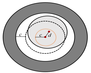
The gap variable is the difference between the clearance (
c) and the distance between the connection points (
d).
Here Xsrc and
Xdst are the undeformed locations of the two connection points, and
usrc and
udst are the corresponding displacements.