Theory for the Thermoelectric Module Component
Thermoelectric modules are devices which use thermoelectricity (Peltier effect) to transfer heat from a source to a sink.
Device Description
They are composed of thermocouples, each consisting of p-type and n-type semiconductors, connected electrically in series and thermally in parallel and sandwiched between two high thermally conductive but low electrically conductive ceramic plates, as described on Figure 4-11 below.
Figure 4-11: Thermoelectric module schematic description.
See Theory for the Thermoelectric Effect Interface for details about the Peltier effect.
Heat Rate
In heating and cooling operating modes of the thermoelectric module (that is, no heat generation), the heat rates at the cold and hot junctions of each thermocouple are due to Peltier effect, Joule heating, thermal conduction, and heat storage:
(4-91)
(4-92)
where
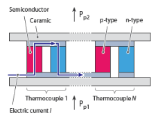
S (SI unit: V/K) is the Seebeck coefficient of the thermocouple
I (SI unit: A) is the electric current operating in the module
Re (SI unit: Ω) is the electrical resistance of the thermocouple
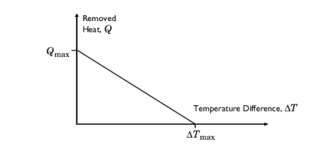
ΔT (SI unit: K) is the temperature difference between the two sides of the module
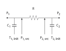
R (SI unit: K/W) is the thermal resistance of the thermocouple
Chot and Ccold (SI unit: J/K) are the thermal capacitances on each side of the module
For a steady-state problem the temperature does not change with time and the heat storage terms disappear.
The Peltier effect is a cooling effect at the hot junction, and a heating effect at the cold junction.
In Equation 4-91 and Equation 4-92 the assumption of a symmetric distribution of Joule heating at the hot and cold junctions has been made.
Thermocouple Electrical and Thermal Resistances
As the p-type and n-type semiconductors are connected electrically in series, the electrical resistance Re of each thermocouple is expressed as:
where Re,p and Re,n (SI unit: Ω) are the electrical resistances of the p-type and n-type semiconductors.
And as they are connected thermally in parallel, the thermal resistance R of each thermocouple is expressed as:
where Rp and Rn (SI unit: K/W) are the thermal resistances of the p-type and n-type semiconductors.
Thermocouple Seebeck Coefficient
Finally, the Seebeck coefficient S of each thermocouple is expressed as:
Total Heat Rate
The total heat rate through the module is obtained by summing the heat rates in each thermocouples.
Network Representation
The following network representation corresponds to Equation 4-91 and Equation 4-92:
Figure 4-12: Thermal network representation of a thermoelectric module.
See Ref. 18 and Ref. 19 for details about the network representation of thermoelectric modules.
Performance Graphs for Thermoelectric Coolers
It is usual to characterize thermoelectric coolers through graphs showing the heat removed from the cold side of the module, Q, in function of the difference of temperature ΔT between the hot and cold sides, the input intensity I, and the ambient temperature.
Linearized Model at Given Intensity and Ambient Temperature
This model establishes a linear relation between the removed heat and the temperature difference, as shown on the figure below:
Qmax is the maximum amount of heat that the thermoelectric cooler can remove, when there is no temperature difference between the two sides of the module.
The linear curves from (ΔT=0, Q=Qmax) to (ΔT=ΔTmax, Q=0) define the removed heat Q as:
Note that this relation is valid when the temperature difference satisfies:
Then the powers applied at the cold and hot sides are respectively:
P=-Q (removed heat)
P=Q + ReI2 (waste heat, including Joule heating)
For cases where the current through the device varies, the performance parameters should be made a function of the current.
General Model
The removed heat may be defined as a more general function of the temperature difference and other parameters such as the temperature at the hot side.