Modeling Layered Materials
The Heat Transfer interfaces contain several lumped conditions for modeling heat transfer in layered materials: Thin Layer, Thin Film, Fracture, and Thin Rod.
In addition, standalone physics interfaces are available for the modeling of heat transfer by conduction, convection and radiation in thin structures:
Either the Solid, Fluid, or Porous Medium feature is available by default in each of these interfaces.
The features mentioned above are the counterparts of domain features for the modeling of heat transfer in solid, fluid, and porous thin structures that can be represented as boundaries or edges, as described in Table 4-2.
All these functionalities have in common the fact that the thin domains they model are lumped into boundaries (for Thin Layer, Thin Film and Fracture) or 3D edges (for Thin Rod).
Reduced Mesh Element Number
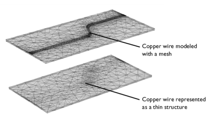
A significant benefit is that a thin structure can be represented as a boundary instead of a domain and a rod can be represented as a 3D edge. This simplifies the geometry and reduces the required number of mesh elements. Figure 4-4 shows an example where a thin structure significantly reduces the mesh density.
Figure 4-4: Modeling a copper wire as a domain (top) requires a denser mesh compared to modeling it as a boundary with a conductive layer (bottom).
Thin Structure as an Extra Dimension
To model heat transfer through the thickness of a thin structure, or multiple sandwiched layers with different material properties and thicknesses, COMSOL Multiphysics gives the possibility to create a product space between the dimensions of the boundary and an additional dimension. This is realized by the Extra Dimension tool through either the General option of the Thin Layer (Heat Transfer Interface) and Solid (Heat Transfer in Shells Interface), Thin Film (Heat Transfer Interface) and Fluid (Heat Transfer in Shells Interface), or Fracture (Heat Transfer Interface) and Porous Medium (Heat Transfer in Shells Interface) features.
Adding Extra Dimensions to a Model and Using Extra Dimensions in the COMSOL Multiphysics Reference Manual.
An additional 1D segmented line represents the thickness of the thin structure. The number of mesh points for each interval of the extra dimension is set to 2 by default.
Tangential and Normal Gradients
In thin structures, the tangential gradient and the normal gradient can be more appropriate to express the governing equations.
The normal gradient is the projection of the gradient operator onto the normal vector, n, of the boundary representing the thin structure. This is mathematically expressed for any scalar field T as:
The tangential gradient removes the normal component from the gradient operation, so that only tangential components remain. This is mathematically expressed for any scalar field T as:
The gradient operator is then split into a tangential part and a normal part:
(4-59)
This relation simplifies to:
when tangential heat transfer is dominant or negligible. These results will be useful in the next sections describing heat transfer in the different thin structures.
Equation 4-59 is valid for flat layered shells. For the curved ones, the gradient expression should account for the surface area and the scaling of each layer. The gradient in the product geometry of a curved layered shell with variable thickness can be written as:
with
where
Xr are the reference surface coordinates
z is the extra-dimension thickness coordinate (varying between 0 and d)
zoff is the relative midplane offset
d is the layered material thickness
It should be noted that when an extra dimension is used, the equations are written from the point of view of the extra dimension. In particular, the dtang() operator would correspond to n since it performs the derivation along the extra line. In the thin structure boundary, dtang() would correspond to t.
In some applications, it is required to model variable thickness layers. This is achieved by scaling the constant thickness of the layer, d, using a thickness factor, lsc, which can be a function of the surface coordinates. The deformation gradient in a scaled product geometry of a curved layered shell can be written as
Area Scale Factor
For a curved layered shell, the change in surface area of each layer should be accounted for while integrating the governing equations. The area scale factor for each layer of the layered material can be defined as
Thermal Conductivity Tensor in Local Boundary Systems
The thermal conductivity k describes the relationship between the heat flux vector q and the temperature gradient T as in
which is Fourier’s law of heat conduction (see also The Physical Mechanisms Underlying Heat Transfer).
The tensor components can be specified in the local coordinate system of the boundary, which is defined from the geometric tangent and normal vectors. The local x direction, exloc, is the surface tangent vector t1, and the local z direction, ezloc, is the normal vector n. Their cross product defines the third orthogonal direction such that:
From this, a transformation matrix between the local coordinate system and the global coordinate system can be constructed in the following way:
The thermal conductivity tensor in the local coordinate system, kbnd, is then expressed as