|
|
|
|
|
|
|
|
||
|
|
|||
|
|
|
||
|
|
|
|
•
|
In 2D components, select between Plane of symmetry (default), Two perpendicular planes of symmetry, or Sectors of symmetry.
|
|
•
|
In 2D axisymmetric components, only the Plane of symmetry option is available.
|
|
•
|
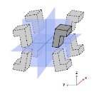
In 3D components, select between Plane of symmetry (default), Two perpendicular planes of symmetry, Three perpendicular planes of symmetry, or Sectors of symmetry.
|
|
•
|
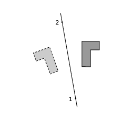
In 2D components, the symmetry plane is defined by two points. If the Selection method is Coordinates, set the x and y coordinates of the First point on plane of reflection and of the Second point on plane of reflection. Else, if the Selection method is Point Selection, you can directly select the points from the Graphics window. In the Selection of First Point and Selection of Second Point sections, first use the Active button to toggle between turning ON
|
|
•
|
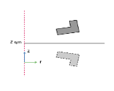
In 2D axisymmetric components, the symmetry plane is parallel to the z=0 plane. If the Selection method is Coordinates, set the z coordinate of plane of reflection, zsym. Else, if the Selection method is Point Selection, you can directly select the point from the Graphics window. In the Selection of the Point Defining the Plane of Reflection section, first use the Active button to toggle between turning ON
|
|
•
|
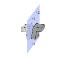
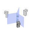
In 3D components, the symmetry plane is defined by three points. If the Selection method is Coordinates, set the x, y, and z coordinates of the First point on plane of reflection, the Second point on plane of reflection, and the Third point on plane of reflection. Else, if the Selection method is Point Selection, you can directly select the points from the Graphics window. In the Selection of First Point, Selection of Second Point, and Selection of Third Point sections, first use the Active button to toggle between turning ON
|
|
•
|
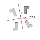
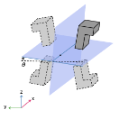
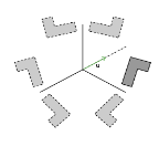
In 2D components, the planes intersection line is along the out-of-plane direction. The Point at the intersection of symmetry planes and the Rotation angle from Cartesian axis, θ, should be defined.
|
|
•
|
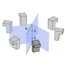
In 3D components, the Planes intersection line can be set Along the x-axis, Along the y-axis, or Along the z-axis. A Point at the intersection of symmetry planes and the Rotation angle from Cartesian axis, θ, should be defined. The position of the point along the intersection line can be arbitrary as it does not change the planes definition. The direction of the angle θ can be checked on the figure displayed below the settings, for each case of alignment of the intersection line.
|
|
•
|
In 2D components, the symmetry axis is the out-of-plane vector, and the center of the symmetry must be defined. Set the x and y coordinates of the Point of central symmetry.
|
|
•
|
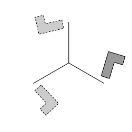
In 3D components, the symmetry axis is defined by two points. Set the x, y, and z coordinates of the First point defining sector symmetry axis and the Second point defining sector symmetry axis.
|
|
|