Working With a Draft of the Model
It may have crossed your mind that saving a new model version requires several steps — especially as compared to just pressing Ctrl+S for a model opened from the file system. You need to open the Save window, perhaps think of a comment describing your changes (although the comment is not required), and then click the Save button (). You might even realize after saving multiple versions that your modeling work has gone in the wrong direction. You would then have a version history cluttered with unwanted versions.
A more lightweight option when working on a model is to save a draft of the model. You can save versions of this draft without affecting the original model. Once you are happy with your draft, you can save it back as a new version of the original model. You may of course choose to discard your draft altogether — instead opening the original model and, perhaps, starting a new draft.
Starting a Draft
You are going to continue the modeling of the wrench using a draft. Make sure that you have opened the latest (top) version in the Versions window.
Add a generic steel material for the wrench and save your work as a new draft.
1
Right-click Component 1>Materials () and select Add Material from Library ().
2
In the Add Material window, click to expand the Built-In tree node. Scroll down to find Structural steel, right-click, and select Add to Component 1.
3
Close the Add Material window.
4
From the File menu, select Save Draft (). You can also press the keyboard shortcut Ctrl+S.
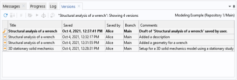
You have created a first version of a draft of the model. You can see this draft version as a new row in the Versions window on top of the three versions of the original model. The draft version uses a separate pen icon () to distinguish it from the regular versions (). Note that the regular versions belong to the original model, not the draft itself — they are included in the table to make it easier for you to track where the draft originated from.
Saving Additional Draft Versions
Specify the load applied to the wrench and save your draft changes.
1
Select Parameters 1 () in the Model Builder window.
2
In the Settings window’s Parameters table, enter these settings:
-
In the Name column, enter F.
-
In the Expression column, enter 150[N].
-
In the Description column, enter Applied Force.
3
From the File menu, select Save Draft ().
Selecting Save Draft a second time creates a second version of your draft — the Versions window now shows two draft versions and three regular versions. As for the regular versions of the original model, you can inspect an older draft version by selecting the row in the table and clicking Open ().
A draft is a model in its own right in the database — existing side by side with the original model. You can switch back and forth between them in the COMSOL Desktop simply by opening one or the other. To demonstrate this:
1
From the File menu, select Open From ().
2
In the Open window, choose your database, Modeling Example, in the list of options.
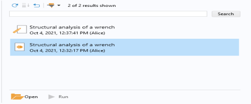
The Open window shows the latest version of the draft () and the latest version of the original model () in the search result.
3
Model Manager detects that there is an ongoing draft of the original model with a draft version newer than the latest version of the model. A dialog box is shown in which you can choose to open that draft version instead.
4
Select the top node in the tree in the dialog box and click Open to open the original model. The latest version of the model is opened in the COMSOL Desktop —neither the Structural steel node nor the Parameters setting is present in the model tree, as expected.
You could at this point continue working with the original model, thereby implicitly discarding your draft work. The draft itself can be manually deleted from the database at some later time.
Choosing instead to continue with your draft, open its latest version again:
1
From the File menu, select Open From ().
2
In the Open window, choose your database in the list of options.
3
Finish the component setup by defining boundary conditions and mesh settings:
1
Right-click Solid Mechanics (solid) () and select Fixed Constraints ().
2
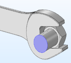
In the Graphics window, rotate the geometry and select the front surface of the partially modeled bolt. The Boundary number in the Selection list is 35.
3
Right-click Solid Mechanics (solid) () once more and select Boundary Load ().
4
5
In the Settings window for Boundary Load, under Force, select Total force as the Load type and enter -F in the text field for the z component.
6
Select Mesh 1 (). In the Settings window for Mesh, under Physics-Controlled Mesh, select Finer from the Element size list.
7
Click the Build All () button in the Settings window.
With the basic setup finished, select Save Draft () in the File menu to save a third draft version.
Finishing Your Draft
With the component setup finished, it is time to save your draft work back to the original model:
1
From the File menu, select Save as Version ().
The Save window opens with your database preselected in the list. The header reads Save version from draft as a new version of the original model will be saved from the draft.
2
Write Finished model for the von Mises stress in a steel wrench in the Comments field.
3
Click the Save button ().
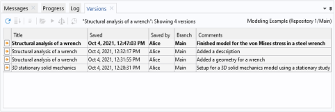
Open the Versions window to see that all draft versions are now gone and replaced by your new, fourth, version of the original model.