|
•
|
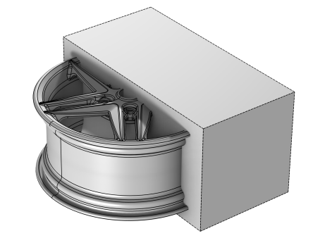
Construction geometry objects are removed by the Form Union/Assembly node.
|

|
•
|
In the settings for geometric primitives, in the section Assigned Attributes, select the check box Construction geometry (cleared by default).
|
|
•
|
In the settings for operation features, in the section Assigned Attributes, from the Construction geometry list choose On. The default option Inherit means that the resulting object becomes construction geometry if all input objects are construction geometry. Choose Off to never output construction geometry objects.
|
|
•
|
Select a number of primitive geometry objects in the Graphics window (or edges or vertices if you are in the 2D sketch visualization mode). Then right-click, and, from the context menu, choose Construction geometry to toggle the Construction geometry check box for the corresponding feature.
|
|
•
|
From the Sketch ribbon tab or toolbar, in the Draw Settings section, select the Construction toggle button (cleared by default) to create construction geometry when using the tools in the Draw section of the toolbar.
|