You are viewing the documentation for an older COMSOL version. The latest version is available here.
Domain Point Probe
Use a Domain Point Probe () to monitor the development of a real or complex-valued number from a dynamic simulation (a time-dependent, frequency-domain, or parametric study). By default, a Point Probe Expression subnode is added, or right-click Domain Point Probe to add additional nodes.
Point Selection
When working with multiple frames, select a FrameSpatial, Material, Geometry, or Mesh — followed by the coordinate names, typically (x, y, z) or (X, Y, Z) in 3D depending on the physics.
For 3D models, select a Line entry method: Point and surface normal (the default), Point and direction, Two points, or None to define a location for the point where you want to add a probe.
For Point and surface normal, Point and direction, or Two points, enter a Depth along line or use the slider to select a value between 0 and 1 to determine the probe location along the line anywhere from the starting point (0) to the ending point (1).
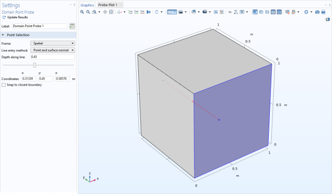
For Point and surface normal, click at a position on the surface of the geometry in the Graphics window to define a point. The direction becomes the inward surface normal as defined by the geometry, which for an exterior boundary means that the probe location can be anywhere from the start position to the end of the geometry in the normal direction. See the figure below.
For Point and direction, click at a position on the surface of the geometry in the Graphics window to define a point. The direction becomes that of a ray directed away from the point in the current camera view (that is, the direction depends on the view).
For Two points, from the Point being modified list, select First point and click on the geometry in the Graphics window to define the first point (starting point). Then select Second point and click to define the second point (endpoint) to define a line between the two points.
Figure 5-6: A point probe location defined as the location that is at 45% along the line defined by a point and a surface normal.
In 3D and for the line entry method None in 3D, enter Coordinates: enter x and y coordinates (2D) or x, y, and z coordinates (3D). You can also adjust the computed coordinates when you use any of the other line entry methods in 3D.
Select the Snap to closest boundary check box to snap the point to the boundary of the geometry closest to that point when the probe is evaluated.
Process Control Using a PID Controller: Application Library path COMSOL_Multiphysics/Multiphysics/pid_control