The Packed Bed Feature
The Packed Bed feature, available to users of the Chemical Reaction Engineering Module, adds a domain feature that can simulate regions filled with reactive porous pellets, as in packed bed reactors. Below the theory for the Packed Bed feature in the Transport of Concentrated Species interfaces is presented.
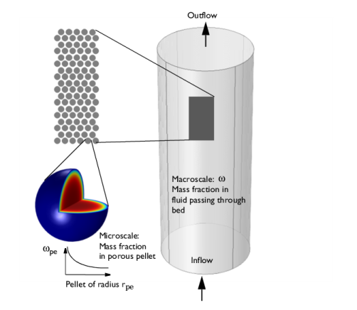
The pellets in the bed are simulated with the Extra Dimension technology provided by the COMSOL software: A 1D, 2D, or 3D domain represents the bed volume. The extra dimension is the added radial microscale dimension inside each pellet.
Figure 3-6: Schematic showing the macroscale (bed volume) and the microscale (pellet).
The equations of mass and momentum transfers inside the pellets are solved on an extra dimension attached to the 1D, 2D, or 3D physics interfaces, including axisymmetric cases.
The equations inside the spherical pellet are solved as a spherical transport equations on a nondimensional radial coordinate on the domain 0-1.
The model equations assume spherical particles (pellets) of a radius rpe. Modeling assumptions for cylinders, flakes, and user-defined shapes can also be used. Consider the microscale mass fraction ωpe,i inside an individual porous pellet or pellets, and the macro mass fraction ωi in the packed bed volume.
The pellet radius input can be:
The model equations in the macroscale (base geometry) for the species mass fraction i and velocity (Darcy’s Law) are, for example:
(3-66)
(3-67)
εb is the bed porosity.
The dependent variable, ωi, represents the interparticle mass fraction (for each chemical species i) in the fluid flowing between the pellets.
Ji is the diffusive mass flux of species i.
Ri is the species reaction rate (kg/(m3·s)) in the bed. This corresponds to reactions occurring in the pore space outside of the pellets. Note, that Ri is the reaction rate per unit volume of bed.
Qm is the mass source (kg/(m3·s)).
Looking inside a pellet: Assuming no concentration variations in the space-angle (θϕ) direction, but only in the radial (r) direction of the spherical pellet allows a spherically symmetric reaction-diffusion transport equation inside the pellet. If rdim (SI unit: m) is the spatial radial coordinate in the pellet, and rpe is the pellet radius, the nondimensional coordinate r = rdim/rpe can be defined. The modeling domain on r goes from 0 to 1.
Figure 3-7: Modeling domain in a pellet for dimensional (top) and nondimensional (bottom) coordinates.
A shell mass balance across a spherical shell at radius rdim (SI unit: m), and a subsequent variable substitution r = rdim/rpe gives the following mass transport equation on the pellet domain 0 < r < 1, Equation 3-21 becomes
(3-68)
N is the number of pellets per unit volume of bed, , Vpe is the pellet volume.
εpe is the pellet (microscale) porosity.
ωpe,i is the intraparticle species mass fraction of fluid volume element inside the pore channel in the pellet.
Jpe,i is the mass flux for species i inside pellet. It is similar to the mass flux in Transport of Concentrated Species.
upe is the velocity of mass bulk in the pellet.
Rpe,i is the pellet reaction rate for species i. This corresponds to reactions taking place inside the pellets. Note that the user input of Rpe,i is per unit volume of pellet.
The velocity u is calculated from pressure gradient,
κpe is the permeability inside pellet.
μpe is the dynamic viscosity inside pellet.
The equation for pressure ppe (base on Equation 3-67) on the pellet domain, 0 < r < 1, is
(3-69)
The mass flux Ji in Equation 3-22, with diffusion model being Mixture-averaged, is
(3-70)
where De,iT is the effective thermal diffusion coefficient, and Dim is
If the diffusion model is Maxwell-Stefan, the equation for mass flux Ji is
(3-71)
where dk is
where De,ik is the effective binary diffusion coefficient. It depends on the porosity εpe, tortuosity τ, and binary diffusion coefficient Dik
The available models for the porous media tortuosity are the one by Millington and Quirk (Ref. 4),
(3-72),
the Bruggeman model,
(3-73)
and the Tortuosity model, where the tortuosity expression is entered as user defined input.
These are readily used for both gaseous and liquid fluids along with various types of pellet shapes.
Equation 3-22 and Equation 3-69 can be solved for two types of boundary conditions at the interface between the pellet surface and the fluid in this feature.
Mass fraction constraint: assuming that all resistance to mass transfer to/from the pellet is within the pellet and no resistance to pellet-fluid mass transfer is on the bulk fluid side. The mass fraction and pressure in the fluid will thus be equal to that in the pellet pore just at the pellet surface: and . These constraints also automatically ensure flux continuity between the internal pellet domain and the free fluid domain through so-called reaction forces in the finite element formulation.
Film resistance (mass flux): The flux of mass across the pellet-fluid interface into the pellet is possibly rate determined on the bulk fluid side by film resistance. The resistance is expressed in terms of a film mass transfer coefficient, hDi, such that:
(3-74),
where Ni, inward is the mass flux from the free fluid into a pellet and has the unit kg/(m2·s), Mi is the molar mass.
With the film resistance formulation above, the equation for mass transfer (Equation 3-22) needs to be amended for flux continuity so that
(3-75)
where Sb (SI unit: m2/m3) is the specific surface area exposed to the free fluid of the packed bed (not including the inside of the pores).
For the case of randomly packed spherical pellets, the specific surface area exposed to the free fluid is (Ref. 5):
(3-76)
The total mass source Qmass is
The equation for pressure (Equation 3-69) becomes
(3-77)
The mass transfer coefficient in Equation 3-27 can be computed from the fluid properties and flow characteristics within the porous media. For this, the Sherwood, Sh, number defined as the ratio between the convective mass transfer coefficient and the diffusive mass transfer coefficient is often used:
where L is a characteristic length (for spheres, typically the radius), and D is the diffusion coefficient in the fluid. From the Sherwood number definition, the mass transfer coefficient can be computed.
Three commonly used empirical expressions for the calculation of the Sherwood number are the Frössling relation (Ref. 6):
(3-78),
which was measured on pellets in the size region 1 mm, the Rosner relation (Ref. 7)
(3-79),
and the Garner and Keey relation (Ref. 6)
(3-80),
which was measured for Re numbers greater than 250.
All three depend on the Reynolds, Re, and Schmidt, Sc, numbers. The first describing the fluid flow regime (laminar versus turbulent) and the second, the ratio between the viscous diffusion rate and the molecular (mass) diffusion rate. In the expressions, properties such as velocity, u, dynamic viscosity, μ, and density, ρ, of the fluid are included.
Nonspherical Particles
For nonspherical pellets (of any shape), the relations above can be applied approximately by reinterpreting the pellet radius rpe as
(3-81)
(Ref. 8), where Ape is the external surface of a single pellet of any shape. Since the specific surface Spe (SI unit: m2/m3) of one pellet is defined as
it follows by insertion of Equation 3-35 that
.
For a packed bed of which the packing has a porosity εb, the specific surface of the bed will be
or
(3-82)
for any pellet shape. Now rpe and Sb can be calculated for any shape and inserted in equations Equation 3-22, Equation 3-69, Equation 3-28 and Equation 3-77. Some common specific shapes have automatic support:
Cylinders
For cylindrical shapes, applying Equation 3-35 gives
(3-83).
It is common practice to assume that the top and bottom surface of cylindrical pellets have negligible effect on the mass transfer to and from the internals of the pellet, or, . Equation 3-37 then simplifies to
and Equation 3-36 to
Flakes
The derivation for a disc-shaped catalyst pellet is exactly the same as for cylindrical pellets, except that the assumption is reversed about the end surfaces and the envelope surface: , where wflake is the thickness of the disc. This gives
and
.
Heat Source
The heat source of endothermic or exothermic reactions inside the pellet needs to be accounted for in the heat transfer on the bulk level if the heat balance is not solved within the pellet. In this case, thermal equilibrium is assumed in each pellet. To account for the heat evolution in the bulk, the source is averaged across the pellet:
(W/m3)
If there are multiple pellet sizes i in the bed the heat source computed by summing over all sizes:
Here θv,i is the volume fraction of pellet i in the pellet mix.