The Laminar Two-Phase Flow, Level Set (

)
and
Turbulent Two-Phase Flow, Level Set (

) interfaces contain an optional multiphysics coupling boundary feature,
Wetted Wall. It is an exclusive feature that overrides the
Wall feature in the Laminar or Turbulent Flow interface as well as the
No Flow feature in the Level Set interface. It cannot be used in boundaries that have a
Flow Continuity feature in the flow physics interface or a
Continuity feature in the level set physics interface. It is available for laminar flow and turbulent flow with wall functions or automatic wall treatment.
The Wetted Wall boundary condition is suitable for walls in contact with the fluid-fluid interface. When this boundary condition is used, the fluid-fluid interface can move along the wall.
where  ,
, 
and
K is the viscous stress tensor.
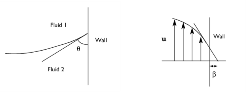
β is the slip length. For numerical calculations, a suitable choice is
β = h, where
h is the mesh element size. The boundary condition does not set the tangential velocity component to zero. However, the extrapolated tangential velocity component is 0 at a distance
β outside the wall (see
Figure 6-1).
The contact angle θw is defined as the angle between the fluid interface and the wall (see
Figure 6-1). For more information, see
Ref. 4 and
Ref. 5. Note that the contact angle is not enforced on boundaries adjacent to porous domains.
The contact angle θw can be defined directly or from Young's equation, which considers the components of the forces in the plane of the surface:
where γs1 is the surface energy density on the fluid 1 — solid (wall) interface and
γs2 is the surface energy density on the fluid 2 — solid (wall) interface.
The Label is the default multiphysics coupling feature name.
The default Name (for the first
Wetted Wall multiphysics coupling feature in the model) is
ww1.
When nodes are added from the context menu, select All boundaries (the default) or select
Manual from the
Selection list to choose specific boundaries.
The Translational velocity setting controls the translational wall velocity,
utr. The list is per default set to
Automatic from frame. The physics automatically detects if the spatial frame moves. This can for example happen if an ALE interface is present in the model component. If there is no movement
utr =
0. If the frame moves,
utr becomes equal to the frame movement.
Select Manual from
Translational velocity selection list in order to manually prescribe
Velocity of moving wall,
utr. This can for example be used to model an oscillating wall where the magnitude of the oscillations are very small compared to the rest of the model. Specifying translational velocity manually does not automatically cause the associated wall to move. An additional Moving Mesh interface needs to be added to physically track the wall movement in the spatial reference frame. For 2D axisymmetric components when
Swirl flow is selected in the physics interface properties, the

component of
utr may also be specified.
Translational velocity can also be set to
Zero (Fixed wall) to force
utr =
0. This is typically used in problems where the mesh is deforming or rotating, but we want the boundary to keep zero velocity. For example, in fixed walls tangential to a
Rotating Domain.