Input (for Geometry Analysis)
The Input subnode is added by default as subnode of the Geometry Analysis node. Use it to specify the boundaries where the wires enter the domain or, in the case of a closed-loop coil, an interior boundary crossed by the wires. Used in combination with the Output (for Geometry Analysis) node, it also defines the direction of the current flow in an open coil (from Input to Output).
When applied on one or more boundaries, a red arrow in the Graphics window will show the direction of the wire. Select the Reverse direction check box to reverse the direction of the wires.
Slanted Cut
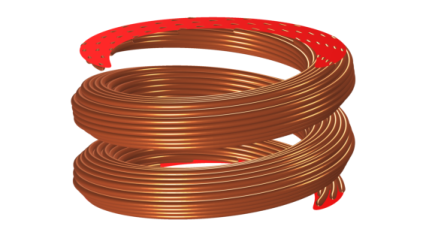
When using the default settings, the wire direction is forced to be orthogonal to the boundary. In some cases, however, the natural direction of the current (or the wires) is at an angle with respect to the input or output normal. A typical example is a helical coil, where the input and output boundaries represent periodicity planes (see Figure 5-3).
Figure 5-3: A helical coil with slanted ends. The slanted cut represents a periodicity plane.
To accommodate this case, the Slanted cut check box allows you to relax the constraints used for determining the coil geometry (it applies the boundary constraint “on average” rather than locally).
For this reason, this setting should not be used when you want to excite multiple separate coils having different shapes using the same input feature. If you have multiple coils with a slanted cut connected in parallel, the recommended approach is to use a separate coil feature for each one of them, and connect the coils in parallel using a circuit (or something equivalent to a circuit).
For an open coil, the Input subnode should never be added to boundaries that are interior to the coil’s domain selection. Note also that an open coil should have its start (Input) and end (Output) on boundaries that are exterior to the domain selection of the parent physics (for example, Magnetic Fields) and of a type that supports closure of the coil by means of an induced surface current density. The latter condition means Magnetic Insulation and, in the frequency domain, Impedance Boundary Condition.