For more information about deformed geometries, see Deformed Geometry and Moving Mesh and Deformed Geometry Features in the COMSOL Multiphysics Reference Manual
|
|
For more information about deformed geometries, see Deformed Geometry and Moving Mesh and Deformed Geometry Features in the COMSOL Multiphysics Reference Manual
|
|
1
|
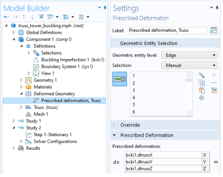
On the Definitions tab, click Deformed Geometry, and select Prescribed Deformation. Alternatively, you can right-click on the Component node and select Deformed Geometry>Prescribed Deformation.
|
|
2
|
In the added Prescribed Deformation node, select the appropriate Geometric entity level, and then select the part of the geometry to perturb.
|
|
3
|
Enter expressions for the Prescribed deformation in terms of the geometry frame coordinates, for example Xg, Yg, and, Zg.
|
|
2
|
On the Definitions tab, click Physics Utilities, and select Buckling Imperfection. Alternatively, you can right-click on the Definitions node and select Physics Utilities>Buckling Imperfection.
|
|
3
|
In the added Buckling Imperfection node, do the following
|
|
a
|
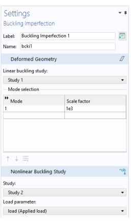
From the Linear buckling study list, choose the study from which the imperfection mode shapes are to be selected. Only studies containing a Linear Buckling study step are shown in the list.
|
|
b
|
Under Mode selection, add the buckling modes to include in the Mode column. Also, specify a scale factor for each mode in the corresponding field under Scale factor.
|
|
c
|
To add a Deformed Geometry node with necessary subnodes in which the selected sum of buckling modes are used as predeformation, click the Create button (
|
|
d
|
From the Study list, choose the study that is the nonlinear buckling study. The default, and most common case, is New, in which case the study does not already exist. You can also select any existing Stationary study.
|
|
e
|
From the Load parameter list, choose the parameter to use as a load parameter for ramping up the load. The parameter must be defined under a Parameters node, so you may have to move there to create it. Its purpose is to act as a multiplier to the same load that was used in the linear buckling study.
|
|
f
|
Click the Create button (
 |
|
|
Here, <CritFactor> is the critical load factor in the linearized buckling analysis. This means that the load is increased in 20 decreasing steps, from 0 to about 1.1 times the critical load factor.
|
|
|
Linear Buckling Analysis of a Truss Tower: Application Library path Structural_Mechanics_Module/Buckling_and_Wrinkling/truss_tower_buckling
|