|
|
|
1
|
|
2
|
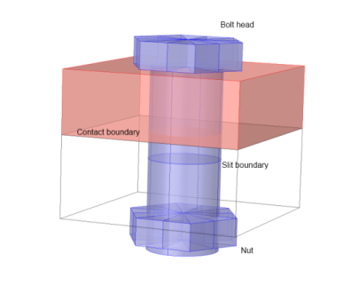
Make sure that there is at least one interior boundary perpendicular to the bolt axis somewhere in the shank. In the following, this boundary is referred to as the slit boundary (Figure 2-24). The slit boundary can be composed of several adjacent boundaries in the geometry.
|
|
3
|
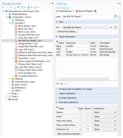
If you are using bolts from the Part Libraries, a slit boundary is predefined, and has the selection name Pretension cut. In order to make this boundary selection visible from the physics interface, select its Keep check box in the Boundary Selections section of the settings for the part instance (Figure 2-25).
|
|
5
|
Add a Bolt Pretension node, in which the pretension force or stress is prescribed for a set of bolts sharing the same data.
|
|
6
|
For each bolt having the same essential data, add a Bolt Selection subnode where its slit boundary is selected.
|
|
7
|
The label of the bolt, which is an input in the Bolt Label section, is used to identify the bolts during result evaluation. A suggestion for the name is automatically generated, based on the base name given in the parent node.
|
|
|
When a bolt is located in a symmetry plane (so that only half the bolt is modeled), and Automatic symmetry detection is selected in the Bolt Selection node, the given pretension force is interpreted as the force in the whole bolt, and not as the force in the half-present bolt. This makes it possible to use the same Bolt Pretension node for a set of similar bolts where some of them are located in symmetry planes.
|
|
1
|
When modeling with beam elements, you will typically use a Polygon with three points to model each bolt (Figure 2-26).
|
|
-
|
You can connect the end of the beam to the edge of the bolt hole (the lower end in Figure 2-26). Then, use the Solid-Beam Connection multiphysics coupling, with Connection type set to Solid Edges to Beam Points. In this case, you select the edge of the bolt hole.
|
|
-
|
You can create a circular boundary having the diameter of the bolt head on the surface of the component (the upper end in Figure 2-26). Then, use the Solid-Beam Connection multiphysics coupling, with Connection type set to Solid Boundaries to Beam Points. In this case, you select the annular solid boundary.
|
|
-
|
Even without creating an extra boundary, you can use the Solid-Beam Connection multiphysics coupling, with Connection type set to Solid Boundaries to Beam Points, general. Then set Connected region to Distance (manual) and enter half the head diameter as Connection radius. In this case, you select the entire boundary on which the bolt head is residing. This method is convenient, but will often give more spurious stresses around the bolt hole, since partial element faces will be connected.
|
|
4
|
Add a Bolt Pretension node, in which the pretension force or stress is prescribed for a set of bolts with the same data.
|
|
5
|
For each bolt having the same essential data, add a Bolt Selection subnode where its slit boundary is selected.
|
|
6
|
The label of the bolt, which is an input in the Bolt Label section, is used to identify the bolts during result evaluation. A suggestion for the name is automatically generated, based on the base name given in the parent node.
 |
|
1
|
Run the study step for the mounting simulation. The predefined study type Bolt Pretension is designed for this. You may need to apply the pretension load in smaller steps, if there are nonlinearities in the system. Then, you select Auxiliary sweep in the Study Extensions section in the settings for the Bolt Pretension study step. Introduce a load ramping parameter, which is used to multiply the pretension forces.
|
|
3
|
Since the pretension degrees of freedom are not solved for in the service load study steps, they must obtain their values from the pretension study step. If the study steps are sequential within the same study, no special action is needed, since the default then is to inherit values from the previous study step. For other cases, go to the Values of Dependent Variables section of the study step, set Values of variables not solved for to User controlled, and then select the pretension study step.
|
|
1
|
In each Bolt Selection node representing a bolt that is not fully pretensioned from the beginning of the study step, select the Sequential tightening check box.
|
|
2
|
A new text field, Pretensioning expression, is now shown. In this text field, you enter a Boolean expression, which evaluates to a nonzero value at the parameter values when the prestress is applied. It may happen more than once, if the bolt is not given its full pretension force at once. An example of such an expression is round(par)==3 || round(par)==11.
|
|
3
|
If you want the bolt prestress (when applied) to have a value that differs from the value given in the parent Bolt Pretension node, change the setting of Pretension type from From parent to another option. Extending the example above, the expression for the pretension force could be 50[kN]*if(par>3.5, 1, 0.6). The only thing that matters here is the value of the force at the parameter values when the pretension force is set, in this example 3 and 11.
|
|
|
If you use the Bolt Pretension study type for the pretension study step, and any other study type to analyze the service loads, the solvers are automatically set up to handle this. The Bolt Pretension study type is actually a special case of a Stationary study step, with the sole purpose of activating the predeformation degrees of freedom. These degrees of freedom are by default not solved for in any other study type.
You enable or disable the solution of individual degrees of freedom under the Dependent Variables node for a certain study step in the solver sequence. If required, begin by clicking Show Default Solver in the study node or in the Solver Configurations node of the study. Then move to the Dependent Variables node, and in the General section, set Defined by study step to User defined.
You can now go to the node for each predeformation degree of freedom below Dependent Variables and adjust the state of the Solve for this state check box.
For more information, see also Dependent Variables and Studies and Solvers in the COMSOL Multiphysics Reference Manual.
|
|
|
Studies and Solvers in the COMSOL Multiphysics Reference Manual
|
|
|
|