For most constraints in the structural mechanics interfaces, you have the possibility to select that certain objects of lower dimensions should be excluded from the main selection. To do this, you must first select Advanced Physics Options. In the settings for a constraint, like for example
Prescribed Displacement, new sections named
Excluded Surfaces,
Excluded Edges, and
Excluded Points will then appear. In these sections, you can select geometrical objects which should be excluded from the main selection when the constraint is applied.
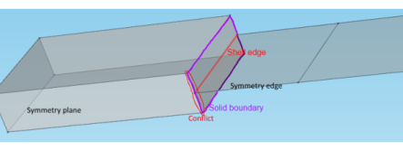
Here you would add a Symmetry condition on a boundary in the Solid Mechanics interface, as well as a
Symmetry condition on an edge in the Shell interface. But at the same time, the displacements on whole boundary where the solid meets the shell are controlled by shell degrees of freedom as an effect of the
Solid-Shell Connection. As a result, on the edge marked with
Conflict in the sketch, the displacements will be controlled both by the symmetry condition is Solid Mechanics, and implicitly through the coupling, by the symmetry condition in the Shell interface. Particularly if the geometry is curved, there is a risk that these constraints are not identical from a numerical point of view. In this case, excluding the conflicting edge from the selected boundary in the Solid Mechanics interface will make the behavior unique and fully predictable.