Use the Section Orientation subnode to define the orientation of a beam cross section using a reference point or an orientation vector. There is always one
Section Orientation subnode for each cross section, and as many
Section Orientation subnodes as needed can be added if the same section appears with different spatial orientations in the structure.
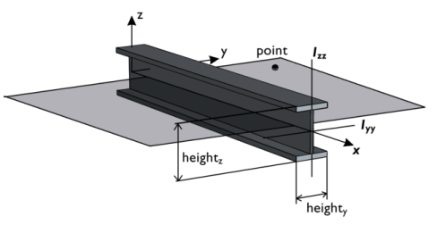
The local x direction is in the edge direction. The positive edge direction can be checked by vector plotting the local edge tangent direction. The coordinates of the reference point define the local
xy-plane together with the beam axis. The local coordinate system (
exl,
eyl,
ezl) is formed using the following algorithm:
Here, p is the reference point, and
m is the midpoint of the beam element. The definition of the local coordinate system is illustrated in
Figure 8-16.
For Orientation vector enter
Orientation vector defining local y direction,
V, and optionally the
Rotation of vector around beam axis φ. The beam orientation is defined similarly to what is described above, with the difference that in this case the direction vector is explicitly defined whereas when an orientation point is used, the direction vector is obtained as the vector from the beam axis to the specified point. The local coordinate system (
exl,
eyl,
ezl) is formed using the following algorithm:
The Rotation of vector around beam axis has the effect of rotating the given vector around the beam axis (using the right-hand rule) before it is used to define the local
xy-plane. This simplifies the input for some cross sections, such as L-shaped profiles, where the principal axes have a direction which is skewed relative to a more natural modeling position. This can be written as
Physics tab with Cross-Section Data or
Section Stiffness node selected in the model tree: