Traps
Many semiconductor devices contain a distribution of traps within the band gap. These traps are associated with donor and acceptor atoms, with other impurity atoms in the bulk of the semiconductor, or with “dangling bonds” that occur at defects or exterior surfaces and grain boundaries. It is useful to consider the processes that can occur when trap states at a given energy, Et, exchange electrons or holes with states in the valence or conduction bands at energy E. This situation is depicted in Figure 3-9. There are four processes that occur, corresponding to the emission and capture of both electrons and holes between states in the bands
.
Figure 3-9: The four processes that contribute to SRH recombination. Left: An electron in the conduction band with energy E is captured by a trap with energy Et (ec). Center left: An electron in a trap at energy Et is emitted to an empty state with energy E in the conduction band (ee). Center right: An electron in a trap at energy Et moves to an empty state in the valence band at energy E. Equivalently a hole in the valence band is trapped (hc). Right: An electron from an occupied state in the valence band at energy E is excited into a trap with energy Et. Equivalently a hole in the trap is emitted (he).
In practice you may want to consider a set of discrete trap levels or a continuum of trap states (with a density of states gt(Et)). Both of these approaches can be accommodated by defining Nt, the density of traps per unit volume at a particular trap energy, Et. For a continuum of trap states, Nt is given by:
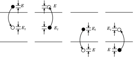
For the trap energy Et, carriers in the conduction band or valence band with energy E make the following contributions to the total recombination or generation rate per unit volume for each process:
(3-80)
where Nt is the number of traps per unit volume, ft is the trap electron occupancy (between 0 and 1), gc(E) is the conduction band density of states, gv(E) is the valence band density of states, and cec(E), cee(E), chc(E), and che(E) are rate constants. The net rate of capture for electrons and holes in the energy interval dE can be written as:
(3-81)
In thermal equilibrium the principle of detailed balance implies the reversibility of each microscopic process that leads to equilibrium. Consequently, at equilibrium, the expressions in the square brackets must be equal to zero. This leads to the following relationships between the rate constants:
In thermal equilibrium the occupancy of the electron traps ft is determined by Fermi-Dirac statistics, fte=1/(1+exp[(Et-Ef)/(kBT)]/gD) (where gD is the degeneracy factor). The above equations can be simplified to yield:
(3-82)
Equation 3-82 applies even away from equilibrium. Substituting this equation back into Equation 3-81, rearranging and integrating, gives the total rate of electron (re) or hole (rh) capture to traps at the specified energy, Et:
where the quasi-Fermi levels have been introduced.
Introducing the constants Cn and Cp, which represent the average capture probability of an electron over the band:
and noting that:
the following equations are obtained:
(3-83)
where:
(3-84)
Equation 3-83 and Equation 3-84 define the electron and hole recombination rates associated with the trap energy level.
For the density-gradient formulation, the following equivalent formulas are used:
(3-85)
(3-86)
The total rate of change of the number of trapped electrons is given by:
(3-87)
Equation 3-87 determines the occupancy of the traps at the level Et. For a continuous distribution of traps the equivalent expression is:
The total recombination rate for electrons and holes is given by integrating Equation 3-83 over all the distributed traps and summing over the distinct discrete traps (denoted by the superscript i), giving the following result:
(3-88)
Finally, the charge resulting from the occupied traps must also be computed. In general the charge on a trap site depends on the nature of the trap. Table 3-1 summarizes the different trap types currently included in the Semiconductor Module.
Note that since “occupied by a hole” is equivalent to “unoccupied by an electron”, an acceptor trap is equivalent to a neutral electron trap. Similarly the donor trap and neutral hole trap types are equivalent.
The total density of traps is given by:
For the discrete states the total number of traps at the discrete level Ei is:
The total charge density, Q, that results from the traps is given by:
(3-89)
Equation 3-89 can be rewritten in the form:
where E0 is an energy within the band gap referred to as the neutral level. E0 is chosen such that:
So if a neutral energy is employed the following equation applies for the charge on the traps:
(3-90)
A neutral level is often a convenient way to characterize a set of traps at a boundary — since the details of the types of trapping sites are frequently not known, but it is possible to assign a neutral level to the boundary using experimental techniques such as capacitance measurements.
Transition between discrete trap levels
Following a similar development as above, the net transition rate R21 from the upper level (2) to the lower level (1) is given by
(3-91)
where Nt,i, ft,i, gD,i, and Et,i are the trap density, trap occupancy, trap degeneracy factor, and trap energy level, respectively, for the ith trap, i=12. This transition rate adds a contribution to the equations for the trap occupancies:
(3-92)