Meshing
The mesh is an important component of any numerical model of a semiconductor device. When assessing a numerical solution it is always important to ensure that the results do not change significantly when the mesh is refined; this is sometimes referred to as grid independence. Different meshing strategies produce optimum results with the finite element and finite volume formulations of the semiconductor equations. The Semiconductor Module includes default mesh suggestions that automatically refine the mesh based on the physics features selected. These mesh suggestions are usually appropriate for both the finite element and the finite volume methods. In some cases manually tuning the default mesh improves performance and helps with the solution process.
The finite volume formulation works best in 2D when triangular or rectangular elements are used. In 3D a swept mesh is currently required (tetrahedral elements are not currently supported for finite volumes in 3D). In this case it is best to mesh with a triangular mesh in the plane of the wafer surface and to sweep the mesh into the wafer. This is particularly important for gate contacts. Figure 2-7 shows some of the techniques that can be used when meshing gates for the finite volume discretization in 3D.
The finite element method (with either the log or linear formulation) works well with all the types of mesh elements available in COMSOL. It is also possible to use adaptive meshing to refine the mesh selectively in regions where the error in the solution is greatest. Adaptive mesh refinement can be added to a Stationary or Time Dependent study step by selecting the Adaptation and error estimates list in the Adaptation and error estimates section.
For finite elements it is particularly important to assess the dependence of the global current conservation on the mesh — this can give a good indication of the overall accuracy of the solution. If current conservation is still poor with a refined mesh tightening the solver tolerances can help (see Solving).
Figure 2-7: Example of a swept mesh appropriate for a gate contact in 3D. The mesh is swept in the direction perpendicular to the gate. The source (left), drain (right), and gate (center) contacts are highlighted in red. The mesh is refined between the contacts, where the Gaussian profile drops off. A geometric sequence with an element ratio of 15 is used to sweep the mesh in the z direction.
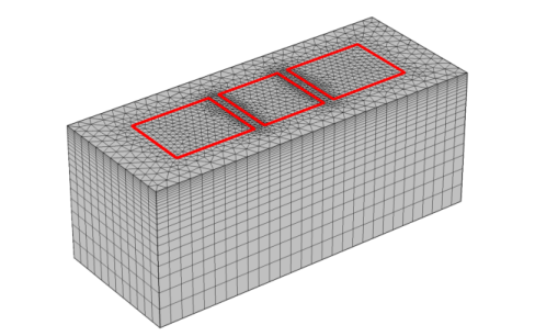
For both finite elements and finite volumes, increasing the mesh density in the vicinity of junctions is important. Note that the Size feature in the meshing sequence can be applied to boundaries, edges, and points, and if the settings are adjusted appropriately this feature can be used to produce a local refinement of the mesh.
For more details on setting up a meshing sequence, see the Meshing chapter in the COMSOL Multiphysics Reference Manual.