Figure 7-1 shows a typical configuration for the flow of fluid in a bearing. The upper boundary is referred to as the journal, and the lower boundary is referred to as the bearing. Damping or lubrication forces act on both surfaces.
In many cases, the gap is sufficiently small for the flow in the thin film to be isothermal. Usually, the gap thickness, h, is much smaller than the lateral dimensions of the geometry,
L. If this is the case, it is possible to neglect inertial effects in the fluid in comparison to viscous effects. Additionally, the curvature of the reference surface can be ignored when
h/
L«1. Under these assumptions, the
Reynolds equation applies. For gas flows under the same conditions, it is possible to derive a modified form of the Reynolds equation, which uses the ideal gas law to eliminate the density from the equation system. Such a
modified Reynolds equation can even be adapted to model the flow of rarefied gases.
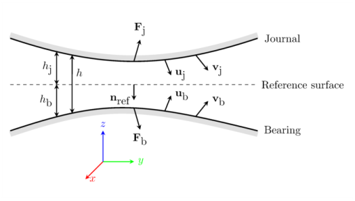
the vector nref points into the bearing and out of the journal. The journal moves with a displacement
uj and velocity
vj from its initial position. Similarly, the bearing moves from its initial position with displacement
ub and velocity
vb. The compression of the fluid results in an excess pressure, p
f, above the reference pressure, p
ref, and a fluid velocity in the gap. At a point on the reference surface, the average value of the fluid velocity along a line perpendicular to the surface is given by the in-plane vector
vave. The motion of the fluid results in forces on the journal (
Fj) and on the bearing (
Fb). The distance to the journal above the reference surface is
hj, while the bearing resides a distance
hb below the reference surface. The total size of the gap is
h=hj+hb. At a given time,
hj=hj1−nref ⋅uj and
hb=hb1−nref ⋅ub, where
hj1 and
hb1 are the initial distances to the journal and bearing, respectively.