Assume that u and
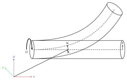
θ are the displacement and deformational rotations of the centroid of the rotor cross section in the spatial frame. Let
X be the material position of a point on the centroid of the rotor. Then, the current position of a point on the rotor can be written as
where Rθ is the rotation matrix due to the rotor deformation and
R is the rotation matrix corresponding to the axial rotation of the rotor. The sequence of the rotations is such that first the cross section of the rotor rotates with the rigid rotation corresponding to the axial rotation of the rotor, followed by the deformational rotation due to bending and twisting of the rotor. Therefore, components of the rotation vector corresponding to deformational rotation of the rotor are observed in the fixed frame. In the corotating frame,
r is the radial vector from the centroid to an arbitrary point in the cross section. The velocity of the point can be obtained by taking the time derivative of
Equation 6-1:
where  is the skew-symmetric tensor corresponding to the angular velocity vector
  of Rθ
of Rθ, and

is the skew-symmetric tensor corresponding to the angular velocity vector
Ω of
R. Here, since
Ω is premultiplied with the rotation matrix to get the time derivative of the rotation matrix, it is the spin tensor observed in the spatial frame.