Use the Space Charge Limited Emission node to model space charge limited emission of electrons from the selected boundary. To use this feature effectively, the following requirements must be met:
where ε0 = 8.854187817 × 10⁻¹² F/m is the vacuum permittivity. The charge density
ρ (SI unit: C/m
3) is due to the released electrons.
The next step is to establish a relationship between the current density J and the charge density
ρ. Consider a surface element
dΩ (SI unit: m
2) parallel to the
yz-plane at some distance
x from the cathode. In a time interval
dt, the number of electrons to cross this surface element is
where v (SI unit: m/s) is the electron velocity.
The velocity at position x is determined from the principle of conservation of energy, noting that the initial particle velocity is assumed to be zero (no thermal contribution),
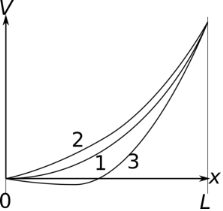
The physical justification for the additional Neumann condition is illustrated in Figure 6-1. If the emitted current is too low (2), it would be possible to release even more electrons, and the electrons would not encounter any potential barrier close to the cathode. However, if the emitted current is too high (3), then they would hit a potential barrier and get sent backward before they could accelerate.

Note that Ref. 1 uses Gaussian units whereas SI units are used here. This explains the additional factor of 4
πε0. Also note the difference in sign convention: here
J is the inward current density, hence it is negative because the released particles are electrons.
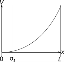
The solution used by the Space Charge Limited Emission feature is to treat the selected boundaries as an emission surface a short distance away from the actual cathode. The space between the emission surface and the cathode should be significantly shorter than the geometric length scale.

The Space Charge Limited Emission node then defines appropriate boundary conditions on the electric potential at the emission surface, by treating the gap between the cathode and the emission surface as a plane parallel vacuum diode. Thus, if V
e is the potential at the emission surface, the cathode potential is 0, and the gap thickness is L, then
Equation 6-7 becomes
Thus, the Space Charge Limited Emission node applies the following boundary condition on the electric potential in the simulation domain:
A negative sign is prepended to the left-hand side of Equation 6-9 because, by the usual COMSOL convention,
n is the outward normal. The model particles are released at the emission surface with initial velocity
When modeling particle-field interaction using the Electric Particle Field Interaction node and the
Bidirectionally Coupled Particle Tracing study step, it is recommended to gradually ramp up the space charge density over the first few iterations. To learn more about ramping up the space charge density term over multiple iterations, see the
Continuation Settings section of the settings window for the
Electric Particle Field Interaction node. The corresponding theory is outlined in the
Stabilization of the Space Charge Density Calculation section.

