PDF

Transverse Modes for a Symmetric Laser Cavity
Introduction
This application demonstrates how to solve for the eigenfrequencies for the lowest order modes in a symmetric laser cavity using the bidirectional Electromagnetic Waves, Beam Envelopes interface. It is assumed that the cavity is two-dimensional and that there are two identical cylindrical mirrors surrounding the air-filled cavity.
The electric field of an electromagnetic wave propagation in 2D space can be expressed as the sum of a number of Hermite–Gaussian modes
(1)
where propagation is assumed along the positive x-direction with the x coordinate measured from the beam waist location, y is the transverse direction with the y coordinate defining the distance from the optical axis, and the field is polarized in the z-direction. The minimum spot radius is given by w0, whereas the spot radius as a function of distance from the beam waist location is given by
where the Rayleigh range is defined by
(2)
and λ is the wavelength. Hn is the Hermite polynomial of degree n. The first polynomials are
and
The vacuum wave number is given by
(3)
where f is the frequency and c is the speed of light.
Notice that the Gouy phase shift around the beam waist location is given
(4)
where
(5)
The wavefront curvature is expressed by
(6)
Notice that in 3D geometry, the square root expression in the amplitude
would be replaced by
and the Gouy phase shift, Equation 4, would be replaced by
where m is the order for another Cartesian transverse Hermite–Gaussian mode that would depend on the transverse z coordinate.
To match the mode to the cavity, the wavefront curvature of the field at the mirrors must match the mirror curvature, Ref. 1. Thus, for a symmetric cavity, where both mirrors have the curvature R and the cavity length is d, Equation 6 states that
(7)
Introducing the stability parameter g, defined by
Equation 7 requires the Rayleigh range to be
(8)
Since the Rayleigh range (see Equation 2) depends on the spot size w0, it is clear that the cavity spot size depends on the ratio between the mirror curvature and the cavity length. For example, when R is infinite a planar cavity having flat mirrors is considered, g = 1, and the Rayleigh range and the spot size become infinitely large. On the other hand, for a concentric cavity, for which g = -1, the beam waist spot size is diffraction limited but the spot radius at the mirrors is large. The confocal cavity, for which g = 0, gives the smallest possible mode volume for a cavity of a given length.
In this application a cavity having a mirror radius of curvature that is 50% longer than the cavity length is studied.
At resonance, the phase shift for propagation half a cavity round trip must equal a multiple times π. Including also a π phase shift from the reflection at the perfectly conducting mirrors, the phase requirement becomes
where q is the longitudinal mode number (the number of nodes in the axial standing-wave pattern).
Using Equation 3, Equation 5, and Equation 8, the resonance frequency can be expressed as
(9)
Equation 9 will be used when comparing to the computed resonance frequencies.
Model Definition
In this application, it is assumed that the cavity boundaries are perfectly conducting. That is, the electric field component in the plane of the boundaries is zero. When using the bidirectional formulation for the Electromagnetic Waves, Beam Envelopes interface, this means that the field at the boundaries are defined by
where E1 and E2 are the solved for slowly varying field envelopes for the forward- and backward-propagating waves, respectively, and φ is a rapidly varying predefined phase function. The phase function φ depends on the frequency, through the wave number (see Equation 3). If an eigenfrequency study would be used for solving the cavity problem, the frequencies inserted in φ would not be the self-consistently solved for eigenfrequencies, but rather the prescribed linearization point frequency f0. The frequency f0 will not approximate the eigenfrequencies good enough, so the returned eigenfrequencies will be wrong. Thus, to accurately find the eigenfrequencies, the problem is formulated as a stationary study solving for both the electric field and the frequencies that self-consistently fulfills the resonance condition. The eigenfrequencies are assumed to be real, as the cavity is closed. The equation solved, in addition to the Helmholtz equation, is only an equation for normalizing the electric field.
To solve for the electric field and the resonance frequency, COMSOL’s complex splitting functionality is used. Thereby the complex variables are split into their corresponding real and imaginary parts before solving. Then all equations will be real and analytical, so an accurate Jacobian can be calculated. This approach solves the problem faster and more robustly. After solving, the complex variables are formed again from the solved for corresponding real and imaginary parts.
Results and Discussion
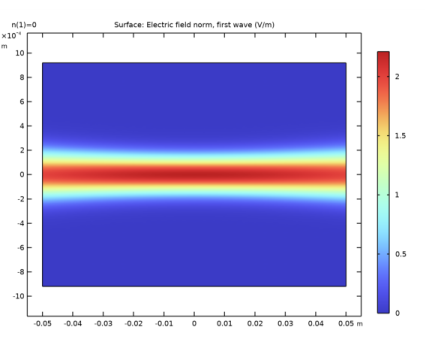
Figure 1 shows the electric field norm for the wave propagating from left to right for a mode with transverse mode number n equal to 0. Notice that since the cavity is 1 dm long and the wavelength is 1 μm, the longitudinal mode number is close to 200,000.
Figure 1: A fundamental transverse mode (n = 0).
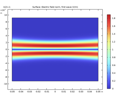
Figure 2 shows a higher-order mode with transverse mode number equal to 1.
Figure 2: A higher-order mode with transverse mode number 1.
Finally, Figure 3 shows a mode for a transverse mode number equal to 2.
Figure 3: A higher-order mode with transverse mode number 2.
Table 1 shows the analytical resonance frequencies from Equation 9 for the three modes solved for.
Reference
1. A. Yariv, Optical Electronics in Modern Communications, 5th ed., Oxford University Press, New York, 1997.
Application Library path: Wave_Optics_Module/Verification_Examples/symmetric_laser_cavity
Modeling Instructions
From the File menu, choose New.
New
In the New window, click  Model Wizard.
Model Wizard
1
In the Model Wizard window, click  2D.
2
In the Select Physics tree, select Optics>Wave Optics>Electromagnetic Waves, Beam Envelopes (ewbe).
3
Click Add.
4
Click  Study.
5
In the Select Study tree, select Empty Study.
6
Study 1
Stationary
In the Study toolbar, click  Study Steps and choose Stationary>Stationary.
Global Definitions
Parameters 1
Add some parameters that define the geometry and the eigenfrequencies searched for.
1
In the Model Builder window, under Global Definitions click Parameters 1.
2
In the Settings window for Parameters, locate the Parameters section.
3
Analytic 1 (an1)
1
In the Home toolbar, click  Functions and choose Global>Analytic.
2
In the Settings window for Analytic, type hermite in the Function name text field.
3
Locate the Definition section. In the Expression text field, type if(n==0,1,if(n==1,2*x,if(n==2,4*x^2-2,0))).
4
In the Arguments text field, type n,x.
Geometry 1
The geometry consists of an intersection of two circles, representing the cylindrical mirrors, and a rectangle, defining the cavity length and height.
Circle 1 (c1)
1
In the Geometry toolbar, click  Circle.
2
In the Settings window for Circle, locate the Size and Shape section.
3
In the Radius text field, type R.
4
Locate the Position section. In the x text field, type R-d/2.
Circle 2 (c2)
1
Right-click Circle 1 (c1) and choose Duplicate.
2
In the Settings window for Circle, locate the Position section.
3
In the x text field, type d/2-R.
Rectangle 1 (r1)
1
In the Geometry toolbar, click  Rectangle.
2
In the Settings window for Rectangle, locate the Size and Shape section.
3
In the Width text field, type d.
4
In the Height text field, type h0.
5
Locate the Position section. From the Base list, choose Center.
Intersection 1 (int1)
1
In the Geometry toolbar, click  Booleans and Partitions and choose Intersection.
2
Click in the Graphics window and then press Ctrl+A to select all objects.
3
Click the  Zoom Extents button in the Graphics toolbar.
4
In the Settings window for Intersection, click  Build All Objects.
5
Click the  Zoom Extents button in the Graphics toolbar.
Definitions
Create another view that make the cavity better fill the graphics window.
View 2
In the Model Builder window, under Component 1 (comp1) right-click Definitions and choose View.
Axis
1
In the Model Builder window, expand the View 2 node, then click Axis.
2
In the Settings window for Axis, locate the Axis section.
3
From the View scale list, choose Manual.
4
In the y scale text field, type 40.
5
Click  Update.
6
Click the  Zoom Extents button in the Graphics toolbar.
Materials
The cavity is filled with air.
Add Material
1
In the Home toolbar, click  Add Material to open the Add Material window.
2
Go to the Add Material window.
3
4
Click Add to Component in the window toolbar.
5
In the Home toolbar, click  Add Material to close the Add Material window.
Electromagnetic Waves, Beam Envelopes (ewbe)
1
In the Model Builder window, under Component 1 (comp1) click Electromagnetic Waves, Beam Envelopes (ewbe).
2
In the Settings window for Electromagnetic Waves, Beam Envelopes, locate the Components section.
3
From the Electric field components solved for list, choose Out-of-plane vector.
Add Physics
Add an ODE interface to solve for the frequency.
1
In the Home toolbar, click  Add Physics to open the Add Physics window.
2
Go to the Add Physics window.
3
In the tree, select Mathematics>ODE and DAE Interfaces>Global ODEs and DAEs (ge).
4
Click Add to Component 1 in the window toolbar.
5
In the Home toolbar, click  Add Physics to close the Add Physics window.
Global ODEs and DAEs (ge)
Global Equations 1
1
In the Model Builder window, under Component 1 (comp1)>Global ODEs and DAEs (ge) click Global Equations 1.
2
In the Settings window for Global Equations, locate the Global Equations section.
3
The equation above represents a normalization of the electric field. The normalization variable nEz will be defined below.
4
Locate the Units section. Click  Select Dependent Variable Quantity.
5
In the Physical Quantity dialog box, type frequency in the text field.
6
Click  Filter.
7
In the tree, select General>Frequency (Hz).
8
9
In the Settings window for Global Equations, locate the Units section.
10
Click  Define Source Term Unit.
11
In the Source term quantity table, enter the following settings:
Electromagnetic Waves, Beam Envelopes (ewbe)
1
In the Model Builder window, under Component 1 (comp1) click Electromagnetic Waves, Beam Envelopes (ewbe).
2
In the Settings window for Electromagnetic Waves, Beam Envelopes, click to expand the Equation section.
3
From the Equation form list, choose Frequency domain.
4
From the Frequency list, choose User defined. In the f text field, type freq1.
Now the electric field will be solved self-consistently for the frequency solved for by the Global Equations 1 node.
Initial Values 1
Insert an approximation of the electric field that makes the nonlinear solver converge to the correct mode fields.
1
In the Model Builder window, under Component 1 (comp1)>Electromagnetic Waves, Beam Envelopes (ewbe) click Initial Values 1.
2
In the Settings window for Initial Values, locate the Initial Values section.
3
Specify the E1 vector as
4
Specify the E2 vector as
Definitions
Now define the integration operator and the variables for normalization of the electric field.
Integration 1 (intop1)
1
In the Definitions toolbar, click  Nonlocal Couplings and choose Integration.
2
Variables 1
1
In the Model Builder window, right-click Definitions and choose Variables.
2
In the Settings window for Variables, locate the Variables section.
3
Mesh 1
Use physics-controlled meshing to create a mapped mesh that resolves the spot radius in the transverse dimension and the Rayleigh range in the longitudinal dimension.
1
In the Model Builder window, under Component 1 (comp1) click Mesh 1.
2
In the Settings window for Mesh, locate the Electromagnetic Waves, Beam Envelopes (ewbe) section.
3
In the NT text field, type 50.
4
In the NL text field, type 30.
5
In the Home toolbar, click  Build Mesh.
6
Click the  Zoom Extents button in the Graphics toolbar.
Study 1
Create a parametric sweep, to look for the fundamental mode and higher-order transverse modes.
Parametric Sweep
1
In the Study toolbar, click  Parametric Sweep.
2
In the Settings window for Parametric Sweep, locate the Study Settings section.
3
4
Solution 1 (sol1)
Solve the stationary problem using complex splitting, to split the complex expressions into their real and imaginary parts. Thereby the expressions become analytical and a correct Jacobian can be calculated. This makes the problem solve faster and more robustly.
1
In the Study toolbar, click  Show Default Solver.
2
In the Model Builder window, expand the Solution 1 (sol1) node, then click Compile Equations: Stationary.
3
In the Settings window for Compile Equations, locate the Study and Step section.
4
Select the Split complex variables in real and imaginary parts check box.
5
Click the  Show More Options button in the Model Builder toolbar.
6
In the Show More Options dialog box, in the tree, select the check box for the node Physics>Advanced Physics Options.
7
Global ODEs and DAEs (ge)
Global Equations 1
1
In the Model Builder window, under Component 1 (comp1)>Global ODEs and DAEs (ge) click Global Equations 1.
2
In the Settings window for Global Equations, click to expand the Discretization section.
3
From the Value type when using splitting of complex variables list, choose Real.
4
In the Study toolbar, click  Compute.
Results
Electric Field
1
In the Model Builder window, expand the Electric Field (ewbe) node, then click Electric Field.
2
In the Settings window for Surface, locate the Expression section.
3
In the Expression text field, type ewbe.normE1.
Electric Field (ewbe)
1
In the Model Builder window, click Electric Field (ewbe).
2
In the Settings window for 2D Plot Group, locate the Data section.
3
From the Parameter value (n) list, choose 0.
4
In the Electric Field (ewbe) toolbar, click  Plot.
5
Click the  Zoom Extents button in the Graphics toolbar.
6
From the Parameter value (n) list, choose 1.
7
In the Electric Field (ewbe) toolbar, click  Plot.
8
From the Parameter value (n) list, choose 2.
9
In the Electric Field (ewbe) toolbar, click  Plot.
Global Evaluation 1
Now compare the analytical mode frequencies to the computed ones.
1
In the Model Builder window, expand the Results>Derived Values node, then click Global Evaluation 1.
2
In the Settings window for Global Evaluation, click  Evaluate.
3
Locate the Expressions section. In the table, enter the following settings:
4
Click  Evaluate.
Table
1
Go to the Table window.
2
Click Full Precision in the window toolbar. At least the first six to seven digits should be the same for the computed and the analytical mode frequencies.