PDF

Aquifer Characterization1
Introduction
This example illustrates how you can use COMSOL Multiphysics’ Optimization interface in combination with a PDE or physics interface to solve inverse-modeling problems (sometimes referred to as parameter estimation or history-matching problems). The modeling techniques presented here in the context of flow in an aquifer with spatially variable hydraulic conductivity are generally applicable for solving underdetermined optimization problems with COMSOL Multiphysics.
Note: This model requires the Optimization Module.
Inverse-Modeling Background
Consider data consisting of the following components:
Inverse modeling is the practice of using data of this kind as input to estimate the unknown parameters of the example, which in this context is called the forward model. In particular, if the number of unknown parameters, n, is larger than the number of measurement values, m, the inverse problem is called underdetermined. This example belongs to this class of inverse problems.
When, as in this case, the forward model is a PDE and the unknown coefficient is a spatially varying random field, the number of unknown parameters is infinite. Even an ordinary finite element discretization typically gives too many unknown parameters by some orders of magnitude. Obtaining a tractable problem that can be solved numerically instead requires a separate regularization.
For underdetermined inverse problems, data fitting alone is not sufficient to single out an optimal solution; achieving this aim requires some additional criterion and an associated penalty function that ranks the solutions according how well they satisfy the criterion in question.
The objective function for an underdetermined inverse problem can thus be written as the sum of a fitness term and a penalty term:
The fitness term
(1)
measures how well the model fits with the observations. Here y denotes an m-dimensional row vector of measurement values; s is an n-dimensional row vector of parameter values; hRn → Rm is the forward model, which maps from parameter values to expected measurements; and R is the m-by-m covariance matrix of measurement errors. Assuming, that the measurement errors are independent and identically distributed with variance σR2, it follows that R = σR2I, where I denotes the m-by-m identity matrix.
The penalty term is relevant for problems where the number of parameters, n, exceeds the number of measurement values, m. It serves to discriminate between solutions with comparable fitness values. Through geostatistical reasoning, Kitanidis (Ref. 2) arrives at the penalty term
(2)
where Q1 is the inverse of the spatial covariance matrix Q ≡ E[(s − Xβ)(s − Xβ)T], with E[ ] denoting the expectation value, X being an n-dimensional row vector whose elements all equal 1, and β referring to the scalar constant mean of the parameter field.
The covariance Q is a symmetric n-b-n matrix, which must be estimated from the measurements or assumed known based on prior information about the process generating s. It is typically assumed that s is a realization of a stationary and isotropic random field, such that elements of the covariance matrix are only a function of the distance between the corresponding points in space: Qij = q(|xixj|). The dependence of q(|xixj|) on distance is usually expressed as a variogram γ(xixj|) = q(0)−q(|xixj|), which is in turn assumed to have a simple functional form with only a few parameters that can be fitted to the data.
Model Definition
Forward Model
Consider a square zone in a confined 2D aquifer of side b = 100 m and with spatially variable hydraulic conductivity, Ks (m/s), which is of interest for transport modeling or other purposes. In this simplified model, assume that the region of interest is surrounded by a practically infinite domain known to have roughly constant hydraulic conductivity, Ks0. Using infinite elements, you can accurately simulate the effect of the infinite exterior domain on the region of interest.
Neglecting any differences in elevation, the hydraulic potential governing the flow through the aquifer and its surroundings can be represented by the pressure head H ≡ p/(ρfg) (m), where p is the fluid pressure (Pa), ρf (kg/m3) is the (constant) fluid density, and g (m/s2) is the acceleration due to gravity. The pressure head, or the hydraulic head, obeys Darcy’s Law
where Qs (1/s) represents sources and sinks. At the modeling domain’s boundary, on the outside of the infinite element zone, any effects of spatial inhomogeneities are negligible and you specify the condition H = 0 to complete the forward model. Note that this choice implies that the variable H refers to the change in hydraulic head from a reference state where no pumping occurs rather than the hydraulic head itself.
Inverse Model
The inverse problem is to estimate the hydraulic-conductivity field in the aquifer using experimental data in the form of hydraulic-head measurements from four dipole-pump tests. More specifically, consider eight wells (represented as points) at the corners and midpoints of the zone being characterized. While injecting fluid at one point, fluid is extracted at the same rate at the opposite point on the rim across the aquifer, and the hydraulic-head values at the six remaining points are recorded. Repeating this procedure for the other three cross-aquifer point pairs, gives a total of 4 sets of 6 observations each. The hydraulic-head measurements are assumed to be independent and have an accuracy on the order of ΔH = 1 cm, resulting in the fitness term (see Equation 1)
(3)
To make use of the experimental data, you must reduce the infinite number of degrees of freedom in the hydraulic-conductivity field to a finite number of unknown parameters. To this end, decompose the quadratic aquifer domain into a 10-by-10 grid of squares of side c = 10 m, and assume that the hydraulic conductivity takes a constant value in each square. The number of parameters characterizing the aquifer is then 100, which gives a well-defined underdetermined inverse model that can be solved quickly as an example problem.
A common assumption in the geological sciences is that spatially distributed parameters follow a geostatistical distribution defined by some parameterized variogram. This COMSOL model uses an exponential variogram of the form
(4)
with variance σ2 = 1 (the sill parameter) and correlation length r = 50 m (the range). For the purpose of this modeling example, assume that the parameters σ and r are known; Kitanidis (Ref. 2) gives methods for estimating their values in the case where they are unknown. Since the covariance must approach zero as the distance between samples increases, this implies a simple covariance function q(|xixj|) = q(h) = eh/r.
Thus, for the penalty term, the elements of the covariance matrix Q are easy to evaluate. Computing the inverse, Q1, would be unnecessarily expensive. Instead, split Equation 2 in two, introducing an auxiliary vector u of the same length as the unknown parameter vector s:
(5)
Solving the linear system Qu = sXβ for the value of u is in general cheaper than inverting Q.
In Figure 1, the eight points on the rim of the area being characterized are numbered pairwise as 1±, 2±, 3±, 4±, with plus and minus signs denoting injection wells and pumping wells, respectively.
Figure 1: Discretization of the hydraulic-conductivity parameter field. Each 10 m-by-10 m square zone is associated with a degree of freedom encoding the constant log10 Ksvalue in the zone. The numbers in blue, outside the square grid, are labels for the dipole-pump pairs (“+” for injection wells and “-” for pumping wells).
Model Data
The data required for setting up the example are supplied in text files included in your COMSOL installation:
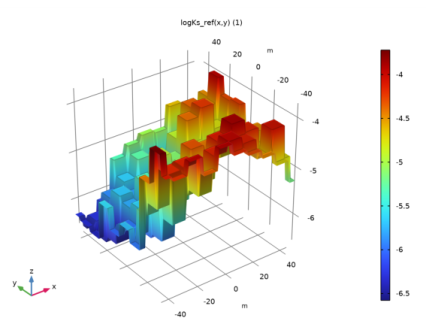
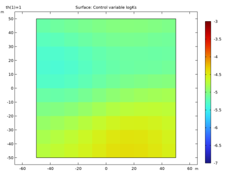
A text file with reference synthetically generated field data, containing the log10 values of the regularized hydraulic-conductivity parameter field that is used to generate fictitious hydraulic-head measurements. This allows you to evaluate the optimization solver’s performance and accuracy, and to test and calibrate the inverse model. For example, you can try out different penalty terms in the objective function and investigate the solution’s dependence on the number of observations used.
The log10 Ks field for the reference model is visualized in Figure 2. It was generated with the exponential variogram, γ, given in Equation 4.
Figure 2: Discretized hydraulic-conductivity field for the reference forward model.
The four simulated dipole-pump tests for the reference forward model give the combined results listed in Table 1, here rounded off to the nearest millimeter; the example uses these numbers as fictitious measurement values.
Although the normalization of the fitness term (see Equation 3) assumes a measurement accuracy of 1 cm, this model (in contrast to Ref. 1) adds no random error component to the above data. This is because the primary aim here is to investigate the software’s performance rather than the viability of the method for aquifer characterization.
Results and Discussion
Figure 3 and Figure 4 show the optimization results for the hydraulic conductivity obtained using only the first measurement series and all four measurement series, respectively. The corresponding values of the total mean square error are 0.318 (0.316) and 0.086 (0.087), where the values in parentheses are those obtained by Cardiff and Kitanidis (Ref. 1). Note that the error estimates are slightly different because Cardiff and Kitanidis include a synthetic measurement error of the order 1% in their observations. Figure 5 compares the results from four different inverse-modeling simulations, using 1, 2, 3, and 4 measurement series, respectively. As the figure shows, the improvement in accuracy is most marked when going from 1 to 2 pump tests (that is, from 6 to 12 observations). Including additional measurements appears to yield comparatively small benefits in accuracy. However, as discussed in Ref. 2, the posterior uncertainty in parameter estimates decreases as more measurements are added.
Figure 3: Inverse-modeling solution for the hydraulic conductivity logarithm parameter field obtained using only the first measurement series (dipole pair number 1).
Figure 4: Hydraulic conductivity obtained by inverse modeling using 24 observations.
Figure 5: Inverse-modeling results for the hydraulic conductivity field with different numbers of hydraulic-head observations taken into account: 6 (upper left), 12 (upper right), 18 (lower left), and 24 (lower right). For a color-scale legend, see Figure 2.
References
1. M. Cardiff and P.K. Kitanidis, “Efficient Solution of Nonlinear, Underdetermined Inverse Problems with a Generalized PDE Model,” Computers & Geosciences, vol. 34, pp. 1480–1491, 2008.
2. P.K. Kitanidis, “Quasi-linear Geostatistical Theory for Inversing,” Water Resources Research, vol. 31, no. 10, pp. 2411–2419, 1995.
Application Library path: Subsurface_Flow_Module/Fluid_Flow/aquifer_characterization
Modeling Instructions
From the File menu, choose New.
New
In the New window, click  Model Wizard.
Model Wizard
1
In the Model Wizard window, click  2D.
2
In the Select Physics tree, select Fluid Flow>Porous Media and Subsurface Flow>Darcy’s Law (dl).
3
Click Add.
4
Click  Study.
5
In the Select Study tree, select General Studies>Stationary.
6
Geometry 1
Square 1 (sq1)
1
In the Geometry toolbar, click  Square.
2
In the Settings window for Square, locate the Size section.
3
In the Side length text field, type 100.
4
Locate the Position section. In the x text field, type -150.
5
In the y text field, type -150.
Array 1 (arr1)
1
In the Geometry toolbar, click  Transforms and choose Array.
2
3
In the Settings window for Array, locate the Size section.
4
In the x size text field, type 3.
5
In the y size text field, type 3.
6
Locate the Displacement section. In the x text field, type 100.
7
In the y text field, type 100.
Point 1 (pt1)
1
In the Geometry toolbar, click  Point.
2
In the Settings window for Point, locate the Point section.
3
In the x text field, type -50,0,0,50.
4
In the y text field, type 0,-50,50,0.
5
In the Geometry toolbar, click  Build All.
6
Click the  Zoom Extents button in the Graphics toolbar.
Global Definitions
Parameters 1
1
In the Model Builder window, under Global Definitions click Parameters 1.
2
In the Settings window for Parameters, locate the Parameters section.
3
As already mentioned, defining the model requires a number of external data files:
To make the data for the log-transmittivity field available in the model, create an interpolation function.
logKs Reference
1
In the Home toolbar, click  Functions and choose Global>Interpolation.
2
In the Settings window for Interpolation, locate the Definition section.
3
From the Data source list, choose File.
4
Click  Browse.
5
6
From the Data format list, choose Grid.
7
Click  Import.
8
In the Label text field, type logKs Reference.
9
Locate the Definition section. Find the Functions subsection. In the table, enter the following settings:
10
Locate the Interpolation and Extrapolation section. From the Interpolation list, choose Nearest neighbor.
11
Locate the Units section. In the Function table, enter the following settings:
12
In the Argument table, enter the following settings:
13
Definitions
Define Infinite Element Domains for the outer squares.
Infinite Element Domain 1 (ie1)
1
In the Definitions toolbar, click  Infinite Element Domain.
2
Variables 1
1
In the Model Builder window, right-click Definitions and choose Variables.
For an initial evaluation of the forward model, use the reference solution’s hydraulic conductivity field. Later, the control variable field for the Optimization interface will override this expression.
2
In the Settings window for Variables, locate the Variables section.
3
Materials
Assign water as the only domain material everywhere. Darcy’s law in general requires separate specifications of the fluid and matrix material properties. In this case, the matrix conductivity is given first by an interpolation field, later by the Optimization interface. Darcy’s Law for time-dependent problems also involves the porosity, but this model is stationary so you can safely ignore the warning about this property being undefined.
Add Material
1
In the Home toolbar, click  Add Material to open the Add Material window.
2
Go to the Add Material window.
3
In the tree, select Built-in>Water, liquid.
4
Click Add to Component in the window toolbar.
5
In the Home toolbar, click  Add Material to close the Add Material window.
Darcy’s Law (dl)
Porous Matrix 1
1
In the Model Builder window, under Component 1 (comp1)>Darcy’s Law (dl)>Porous Medium 1 click Porous Matrix 1.
2
In the Settings window for Porous Matrix, locate the Matrix Properties section.
3
From the Permeability model list, choose Hydraulic conductivity.
4
In the K text field, type 10^logKs0.
This is the conductivity that is applied to the Infinite Element Domain. The center domain is defined as follows:
Porous Medium 2
1
In the Physics toolbar, click  Domains and choose Porous Medium.
2
Porous Matrix 1
1
In the Model Builder window, click Porous Matrix 1.
2
In the Settings window for Porous Matrix, locate the Matrix Properties section.
3
From the Permeability model list, choose Hydraulic conductivity.
4
In the K text field, type 10^logKs.
Hydraulic Head 1
1
In the Physics toolbar, click  Boundaries and choose Hydraulic Head.
Select all outer boundaries.
Next, add the dipole pumps by using the Line Mass Source feature.
Line Mass Source 1
1
In the Physics toolbar, click  Points and choose Line Mass Source.
2
3
In the Settings window for Line Mass Source, locate the Line Mass Source section.
4
In the N0 text field, type if(th==1,N0,0).
The conditional statement allows you to control which dipole pump to activate through the parameter th. Note that a value of zero is the default condition, so setting N0 to zero has no effect on the model equations.
Line Mass Source 2-8
Proceed to create seven additional Line Mass Source features with the following settings:
Mesh 1
1
In the Model Builder window, under Component 1 (comp1) click Mesh 1.
2
In the Settings window for Mesh, locate the Sequence Type section.
3
From the list, choose User-controlled mesh.
Size 1
1
In the Model Builder window, right-click Free Triangular 1 and choose Size.
2
In the Settings window for Size, locate the Geometric Entity Selection section.
3
From the Geometric entity level list, choose Domain.
4
5
Locate the Element Size section. Click the Custom button.
6
Locate the Element Size Parameters section. Select the Maximum element size check box.
7
Size 2
1
Right-click Free Triangular 1 and choose Size.
2
In the Settings window for Size, locate the Geometric Entity Selection section.
3
From the Geometric entity level list, choose Point.
4
5
Locate the Element Size section. Click the Custom button.
6
Locate the Element Size Parameters section. Select the Maximum element size check box.
7
8
Click  Build All.
Study 1
Solve the forward problem to verify that you have implemented the physics correctly.
1
In the Home toolbar, click  Compute.
Results
Hydraulic Head, Forward
The default plot shows the pressure distribution. Modify it to display the hydraulic head instead.
1
In the Settings window for 2D Plot Group, type Hydraulic Head, Forward in the Label text field.
Surface
1
In the Model Builder window, expand the Hydraulic Head, Forward node, then click Surface.
2
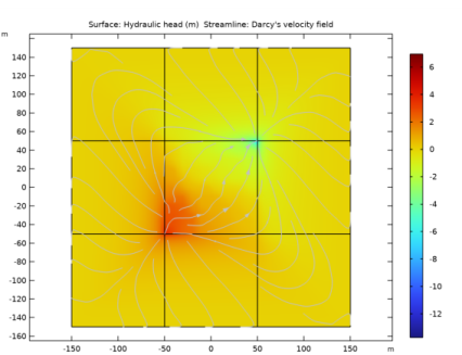
In the Settings window for Surface, click Replace Expression in the upper-right corner of the Expression section. From the menu, choose Component 1 (comp1)>Darcy’s Law>Velocity and pressure>dl.H - Hydraulic head - m.
The result should look like that in the figure below.
Next, set up the auxiliary model for the hydraulic conductivity control variable field and the help variable u.
Add Component
In the Model Builder window, right-click the root node and choose Add Component>2D.
Next, create the auxiliary geometry on which the Optimization interface lives. This geometry is a copy of the aquifer domain, except that you do not need to include vertices at the positions of the sources and sinks.
Add Physics
1
In the Home toolbar, click  Add Physics to open the Add Physics window.
2
Go to the Add Physics window.
3
In the tree, select Mathematics>Optimization and Sensitivity>General Optimization (opt).
4
Click Add to Component 2 in the window toolbar.
5
In the tree, select Mathematics>ODE and DAE Interfaces>Domain ODEs and DAEs (dode).
6
Click Add to Component 2 in the window toolbar.
7
In the Home toolbar, click  Add Physics to close the Add Physics window.
Add Study
1
In the Home toolbar, click  Add Study to open the Add Study window.
2
Go to the Add Study window.
3
Find the Studies subsection. In the Select Study tree, select General Studies>Stationary.
4
Click Add Study in the window toolbar.
5
In the Model Builder window, click the root node.
6
In the Home toolbar, click  Add Study to close the Add Study window.
Geometry 2
In the Model Builder window, under Component 2 (comp2) click Geometry 2.
Square 1 (sq1)
1
In the Geometry toolbar, click  Square.
2
In the Settings window for Square, locate the Size section.
3
In the Side length text field, type 100.
4
Locate the Position section. From the Base list, choose Center.
Definitions (comp2)
You will define the hydraulic conductivity control variable shortly. To make it available on the forward-model’s geometry, use a General Extrusion operator.
General Extrusion 1 (genext1)
1
In the Definitions toolbar, click  Nonlocal Couplings and choose General Extrusion.
2
In the Settings window for General Extrusion, locate the Source Selection section.
3
From the Selection list, choose All domains.
Define an operator for calculating the mean square error. Note that this is an area-weighted average.
Average 1 (aveop1)
1
In the Definitions toolbar, click  Nonlocal Couplings and choose Average.
2
In the Settings window for Average, type mean in the Operator name text field.
3
Locate the Source Selection section. From the Selection list, choose All domains.
To evaluate the penalty function, which is defined in terms of matrix-vector products with discrete control variable degrees of freedom, you need a way to compute a discrete sum over the mesh elements. This can be achieved using an Integration operator of order 0, together with appropriate compensation for the mesh element area.
Integration 1 (intop1)
1
In the Definitions toolbar, click  Nonlocal Couplings and choose Integration.
2
In the Settings window for Integration, type int0 in the Operator name text field.
3
Locate the Source Selection section. From the Selection list, choose All domains.
4
Locate the Advanced section. In the Integration order text field, type 0.
Variables, Domain
1
In the Definitions toolbar, click  Local Variables.
2
In the Settings window for Variables, type Variables, Domain in the Label text field.
3
Locate the Geometric Entity Selection section. From the Geometric entity level list, choose Domain.
4
5
Locate the Variables section. In the table, enter the following settings:
The dest() operator instructs the software to evaluate the enclosed argument at the destination point when evaluating an integral. The result of calling a nonlocal integration coupling with an argument containing the variable dist will therefore depend on where the integral is evaluated.
In this case, a nonlocal integration coupling is used to compute a discrete sum over elements. This is achieved using a single integration point per element and compensating for the corresponding integration point weight. The variable dvol is the volume scale factor that the software uses internally when mapping between dimensionless local element coordinates and the model geometry’s global coordinate system shown in the user interface. The mesh-element volume in the local element coordinate system multiplied by dvol therefore gives the mesh-element volume in the global coordinates. In 2D, the mesh-element area in element coordinates is 1 for quadrilateral meshes and 1/2 for triangular meshes.
Variables, Global
1
In the Definitions toolbar, click  Local Variables.
Add variables for the mean squared error, the mean of the log conductivity and the penalty term.
2
In the Settings window for Variables, type Variables, Global in the Label text field.
3
Locate the Variables section. In the table, enter the following settings:
Note that the penalty function is evaluated using the intermediate variable u, which is computed as the solution of an auxiliary equation. The integration operator int0 together with areaFactor effectively computes the discrete scalar product between the vectors logKs-logKs_mean and u.
Furthermore, note that the model entry appears in red as logKs has not yet been defined in component 2. This will be done in the General Optimization settings.
Covariance function
1
In the Definitions toolbar, click  Analytic.
2
In the Settings window for Analytic, type Covariance function in the Label text field.
3
In the Function name text field, type Q.
4
Locate the Definition section. In the Expression text field, type sigma^2*exp(-x/r).
5
Locate the Units section. In the table, enter the following settings:
6
In the Function text field, type 1.
General Optimization (opt)
In the Model Builder window, under Component 2 (comp2) click General Optimization (opt).
Control Variable Field 1
1
In the Physics toolbar, click  Domains and choose Control Variable Field.
2
In the Settings window for Control Variable Field, locate the Domain Selection section.
3
From the Selection list, choose All domains.
4
Locate the Control Variable section. In the Control variable name text field, type logKs.
5
In the Initial value text field, type logKs_ref.
This is just a temporary initial setting; after creating a plot of the reference solution you will change it to logKs0.
6
Locate the Discretization section. From the Shape function type list, choose Discontinuous Lagrange.
7
Find the Base geometry subsection. From the Element order list, choose Constant.
This gives discontinuous elements of order zero for the control variable logKs, a choice that ensures that each auxiliary-geometry mesh element carries a single degree of freedom.
Global Least-Squares Objective 1
Here, use the measurement file aquifer_characterization_zero.csv to minimize a positive objective contribution that does not correspond to an actual measurement; you will add the real measurements shortly to the first model.
1
In the Physics toolbar, click  Global and choose Global Least-Squares Objective.
2
In the Settings window for Global Least-Squares Objective, locate the Experimental Data section.
3
Click  Browse.
4
To put the penalty term formally on least-squares format — something which is required by the Levenberg-Marquardt solver — enter the square root of the penalty value as a model expression to be compared with the dummy zero measurement.
Value Column 1
1
In the Physics toolbar, click  Attributes and choose Value Column.
2
In the Settings window for Value Column, locate the Value Column section.
3
In the Expression text field, type sqrt(L_penalty).
Domain ODEs and DAEs (dode)
Set up the equation for the auxiliary vector u, which must use the same discretization as the control variable field logKs.
1
In the Model Builder window, under Component 2 (comp2) click Domain ODEs and DAEs (dode).
2
In the Settings window for Domain ODEs and DAEs, locate the Units section.
3
In the Source term quantity table, enter the following settings:
4
Click to expand the Discretization section. From the Element order list, choose Constant.
Distributed ODE 1
1
In the Model Builder window, under Component 2 (comp2)>Domain ODEs and DAEs (dode) click Distributed ODE 1.
2
In the Settings window for Distributed ODE, locate the Source Term section.
3
In the f text field, type (logKs-logKs_mean-int0(u*Q(dist)*areaFactor)).
Mesh 2
Mapped 1
In the Mesh toolbar, click  Mapped.
Distribution 1
1
Right-click Mapped 1 and choose Distribution.
2
In the Settings window for Distribution, locate the Boundary Selection section.
3
From the Selection list, choose All boundaries.
4
Locate the Distribution section. In the Number of elements text field, type 10.
5
Click  Build All.
Definitions (comp1)
Now return to Component 1 and add an alternative definition of variable logKs, mapping the corresponding control variable field from Component 2.
Variables 4
1
In the Model Builder window, under Component 1 (comp1)>Definitions right-click Variables 1 and choose Duplicate.
2
In the Settings window for Variables, locate the Variables section.
3
Component 1 (comp1)
Because the measurements are to be compared with the solutions of Component 1, define the least-squares objective contributions in this model.
Add Physics
1
In the Home toolbar, click  Add Physics to open the Add Physics window.
2
Go to the Add Physics window.
3
In the tree, select Mathematics>Optimization and Sensitivity>General Optimization (opt).
4
Click Add to Component 1 in the window toolbar.
5
In the Home toolbar, click  Add Physics to close the Add Physics window.
General Optimization 2 (opt2)
Least-Squares Objective 1
1
Right-click Component 1 (comp1)>General Optimization 2 (opt2) and choose the domain setting Least-Squares Objective.
2
3
In the Settings window for Least-Squares Objective, locate the Experimental Data section.
4
Click  Browse.
5
This file has three columns: the first two are coordinate columns defining the measurement location for the value found in the third column. The index 1 in the filename refers to the measurement series number. Thus, this feature contains the contribution from the first measurement series to the objective function, corresponding to the experimental parameter value th=1. Once you have set it up, you can duplicate it to conveniently add the contributions from the remaining three experiment series.
6
Locate the Experimental Parameters section. Click  Add.
7
Coordinate Column 1
In the Physics toolbar, click  Attributes and choose Coordinate Column.
Least-Squares Objective 1
In the Model Builder window, click Least-Squares Objective 1.
Coordinate Column 2
1
In the Physics toolbar, click  Attributes and choose Coordinate Column.
2
In the Settings window for Coordinate Column, locate the Coordinate Column section.
3
From the Coordinate list, choose y.
Least-Squares Objective 1
In the Model Builder window, click Least-Squares Objective 1.
Value Column 1
1
In the Physics toolbar, click  Attributes and choose Value Column.
2
In the Settings window for Value Column, locate the Value Column section.
3
In the Expression text field, type comp1.dl.H.
4
In the Column contribution weight text field, type 1/deltaH^2.
The measurements are weighted by the inverse of the square of the measurement error.
Least-Squares Objectives 2-4
Now add the three remaining measurement series, by duplicating the Least-Squares Objective 1 node for each measurement. Make sure you end up with the following nodes and the correct settings:
Study 2
Step 1: Stationary
Before computing the inverse model, test the model setup by computing the forward-model solution corresponding to the reference hydraulic conductivity field mapped from Component 2. First, disable the original definition of the hydraulic conductivity for this study step.
1
In the Model Builder window, under Study 2 click Step 1: Stationary.
2
In the Settings window for Stationary, locate the Physics and Variables Selection section.
3
Select the Modify model configuration for study step check box.
4
In the tree, select Component 1 (Comp1)>Definitions>Variables 1.
5
Click  Disable.
6
In the Home toolbar, click  Compute.
Results
For later comparison with the results of the inverse modeling runs, plot the reference solution for the hydraulic conductivity logarithm in a separate window. You can then let COMSOL Multiphysics update the Graphics window plot while solving.
Surface 1
1
In the Model Builder window, expand the Results>2D Plot Group 3 node, then click Surface 1.
2
In the Settings window for Surface, click to expand the Range section.
3
Select the Manual color range check box.
4
In the Minimum text field, type -7.
5
In the Maximum text field, type -3.
By locking the color range in this way you ensure that the color legend is unaffected by changes in the maximum and minimum values for the control variable field.
6
Click to expand the Quality section. From the Smoothing list, choose None.
No smoothing is necessary because logKs is piecewise constant.
7
In the 2D Plot Group 3 toolbar, click  Plot.
log Ks, 6 Obs.
1
In the Model Builder window, under Results click 2D Plot Group 3.
2
In the Settings window for 2D Plot Group, type log Ks, 6 Obs. in the Label text field.
3
In the log Ks, 6 Obs. toolbar, click  Plot In and choose New Window.
This creates a static plot that is not updated when the solution dataset changes.
Now compute the inverse model for a single measurement series, but first set the initial solution for logKs to a constant value.
General Optimization (opt)
Control Variable Field 1
1
In the Model Builder window, under Component 2 (comp2)>General Optimization (opt) click Control Variable Field 1.
2
In the Settings window for Control Variable Field, locate the Control Variable section.
3
In the Initial value text field, type logKs0.
Study 2
Optimization
1
In the Study toolbar, click  Optimization and choose Optimization.
2
In the Settings window for Optimization, locate the Optimization Solver section.
3
From the Method list, choose Levenberg-Marquardt.
4
In the Optimality tolerance text field, type 0.002.
In order to see how the inverse model result improves as the number of measurements increases, begin by disabling the last three Least Squares Objective nodes.
5
Locate the Objective Function section. In the table, clear the Active check boxes for General Optimization 2 (opt2)/Least-Squares Objective 2, General Optimization 2 (opt2)/Least-Squares Objective 3, and General Optimization 2 (opt2)/Least-Squares Objective 4.
6
Locate the Output While Solving section. Select the Plot check box.
7
From the Plot group list, choose log Ks, 6 Obs..
Disable table output of objective and constraint values.
8
Clear the Keep objective values in table check box.
9
In the Study toolbar, click  Compute.
Results
Pressure (dl)
The solver converges after about 30 iterations and a solution time around 1 minute.
log Ks, 6 Obs.
Compare the plot with that shown in Figure 3.
Evaluate the mean square error as follows:
MSE, 6 obs.
1
In the Model Builder window, expand the Results>Derived Values node, then click Global Evaluation 1.
2
In the Settings window for Global Evaluation, type MSE, 6 obs. in the Label text field.
3
Click Replace Expression in the upper-right corner of the Expressions section. From the menu, choose Component 2 (comp2)>Definitions>Variables>MSE - Area-weighted mean squared error.
4
Click  Evaluate.
The value should be close to 0.32.
Table
1
Go to the Table window.
Finally, compute the inverse model including all four measurement series in a separate study.
To keep the solution for 6 observations, you can either create a new study with the same settings as before or you create a copy of the current solution and modify Study 2. To do so, proceed as follows:
Study 2
Solver Configurations
In the Study toolbar, click  Create Solution Copy.
Optimization
1
In the Model Builder window, click Optimization.
2
In the Settings window for Optimization, locate the Objective Function section.
3
In the table, select the Active check boxes for General Optimization 2 (opt2)/Least-Squares Objective 2, General Optimization 2 (opt2)/Least-Squares Objective 3, and General Optimization 2 (opt2)/Least-Squares Objective 4.
Before hitting the Compute button, prepare the plots.
Results
2D Plot Group 4
Delete the plot group displaying the auxiliary variable u.
1
In the Model Builder window, under Results right-click 2D Plot Group 4 and choose Delete.
2
Click Yes to confirm.
log Ks, 6 Obs.
1
In the Model Builder window, under Results click log Ks, 6 Obs..
2
In the Settings window for 2D Plot Group, locate the Data section.
3
From the Dataset list, choose Study 2/Solution 2 - Copy 1 (5) (sol3).
log Ks, 24 Obs.
1
Right-click log Ks, 6 Obs. and choose Duplicate.
2
In the Settings window for 2D Plot Group, type log Ks, 24 Obs. in the Label text field.
3
Locate the Data section. From the Dataset list, choose Study 2/Solution 2 (3) (sol2).
MSE, 6 obs.
1
In the Model Builder window, under Results>Derived Values click MSE, 6 obs..
2
In the Settings window for Global Evaluation, locate the Data section.
3
From the Dataset list, choose Study 2/Solution 2 - Copy 1 (5) (sol3).
Study 2
Optimization
1
In the Model Builder window, under Study 2 click Optimization.
2
In the Settings window for Optimization, locate the Output While Solving section.
3
From the Plot group list, choose log Ks, 24 Obs..
4
In the Study toolbar, click  Compute.
Results
log Ks, 24 Obs.
Now, compare the plot with that shown in Figure 4.
MSE, 24 obs.
1
In the Model Builder window, under Results>Derived Values click Global Evaluation 2.
2
In the Settings window for Global Evaluation, type MSE, 24 obs. in the Label text field.
3
Click Replace Expression in the upper-right corner of the Expressions section. From the menu, choose Component 2 (comp2)>Definitions>Variables>comp2.MSE - Area-weighted mean squared error.
4
Click  Evaluate.
The value should be approximately 0.086.
 

1
The formulation of this example is courtesy of Mr. Michael A. Cardiff and Prof. Peter K. Kitanidis of Stanford University, who have kindly made their own model version available (Ref. 1).