PDF

Comparison of Different Hydrodynamic Bearings
Introduction
This example compares the load bearing abilities of different hydrodynamic bearings. The simulation is performed using the Rotordynamics Module’s Hydrodynamic Bearing interface. This interface solves the Reynolds equation to compute the pressure developed in a thin fluid film for different bearing types. The bearings included in this example are of plain, elliptic, split-halves, and multilobe type (2, 3, and 4 lobes).
Model Definition
Eight bearings are compared: One each of plain, elliptic, and split-halves type, and five different multilobe bearings. The latter are one two-lobe bearing and two three-lobe and four-lobe bearings. The two three-lobe bearings differ from each other in their relative orientation with respect to the applied load direction, as do the two four-lobe bearings.
The journals rotate inside the bearing with an angular speed of Ω (rad/s). The static position of the journal is obtained such that the net force due to the fluid film in the horizontal direction is zero whereas that in the vertical direction balances the journal weight, W.
The bearing configuration is shown in Figure 1 below.
Figure 1: Bearing configuration. Top row: Plain, elliptic, split halves, two-lobe. Bottom row: Three-lobe (LOP), three-lobe (LBP), four-lobe (LOP), four-lobe (LBP).
On the fluid side, the parameters needed for the computation are the dynamic viscosity, the density at cavitation pressure, and the compressibility. The fluid parameters, whose values are summarized in Table 1, are close to those of lubricating oils used in real bearings.
10-7 Pa-1
Bearing Data
The maximum and minimum clearance, Cmax and Cmin, respectively, of all the bearings are set to the same values in order to make them equivalent.
The initial clearance, hb, assuming that the journal is located at the center of the bearing, is listed in Table 2.
hb = C
The objective is to obtain various parameters in Table 2 for different bearings by setting maximum and minimum values to Cmax and Cmin, respectively. The following sections provide these expressions.
Plain Bearing
Because the initial thickness is uniform, the best choice of C for the plain bearing is C = (Cmax + Cmin)/2.
Elliptic Bearing
The maximum and minimum clearance Cmax and Cmin are known.
Split-halves Bearing
For split-halves bearings, Cmin = C − d, Cmax = C + d, from which one finds C = (Cmax + Cmin)/2 and d = (Cmax − Cmin)/2.
Multilobe Bearings
For multilobe bearings, Cmax = C + d and Cmin = C + d cos(π/N).
Hence, it follows that C = (Cmin − cos(π/N)Cmax)/(1 − cos(π/N)), and d = (Cmax − Cmin)/(1 − cos(π/N)).
Results and Discussion
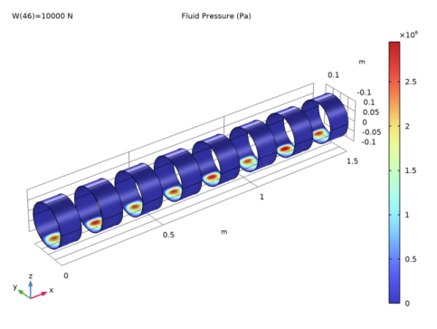
Figure 2 below shows the fluid pressure profile on the bearing.
Figure 2: Fluid film pressure profile.
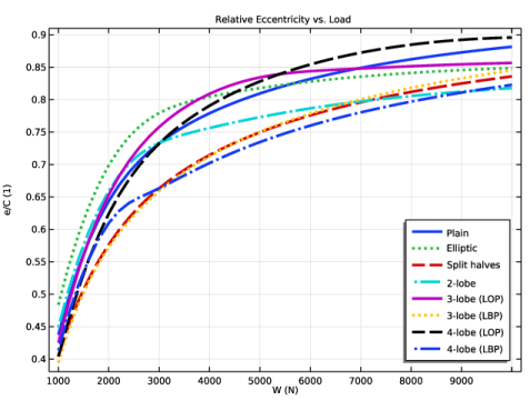
Several results from the simulation provide valuable information about bearing performance. Figure 3 shows a plot of journal eccentricity versus load. The journals that exhibit lower eccentricity are the better ones. From the plot, it seems that the split-halves and 3-lobe LBP (load between pad) bearings have optimum eccentricity in the operating range. For loads higher than 5000 N, the 4-lobe bearing with load on pad (LOP) has the largest eccentricity, while the 4-lobe LBP has the smallest one. The performances of the other bearings lie somewhere in between.
Figure 3: Eccentricity vs. load.
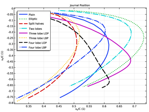
The equilibrium position of the journals is shown in Figure 4 with increasing load W. The y-coordinate of the journal position is plotted on the x-axis, and the z-coordinate is plotted on the y-axis. When the load W is small, all journals tend to move more in the y direction while the movement in the z direction is small. However, as the load increases, they move significantly in the negative z direction and touch the bottom part of the bearing. In the hydrodynamic bearing, two types of forces act on the journal. One, a radial force due to the pressure distribution in the film and other, a tangential viscous force due to the shear in the film. The journal equilibrium position depends on the relative magnitude of these forces. If the shear force is dominant and is enough to support the weight of the journal, equilibrium position is more toward the horizontal direction. For a large journal weight, shear force alone cannot support the journal and a radial force is also needed. In such a case, journal equilibrium position will move in the negative z direction.
Figure 4: Journal position.
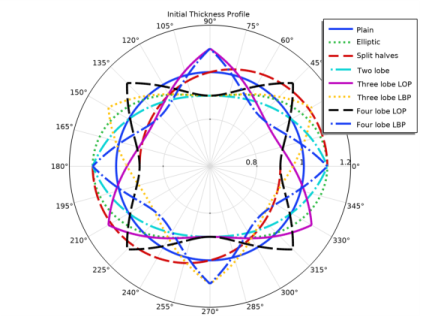
Figure 5 shows the plot of the fluid thickness profile when the journal is concentric with the bearing. The geometric parameters of bearings are set in such a way that the minimum and maximum clearances are the same for all bearings except for the plain bearing, which is kept at the mean position.
Figure 5: Initial thickness profile.
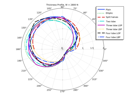
Figure 6 shows a plot of the steady-state (current) thickness profile of the fluid.
Figure 6: Current thickness profile.
Notes About the COMSOL Implementation
In the computation, use an Auxiliary sweep study extension on the load applied by the journal on the bearing to automatically run a loop over the parameter. The Auxiliary sweep functionality is activated in the study step settings.
Application Library path: Rotordynamics_Module/Tutorials/hydrodynamic_bearings_comparison
Modeling Instructions
From the File menu, choose New.
New
In the New window, click  Model Wizard.
Model Wizard
1
In the Model Wizard window, click  3D.
2
In the Select Physics tree, select Structural Mechanics>Rotordynamics>Hydrodynamic Bearing (hdb).
3
Click Add.
4
Click  Study.
5
In the Select Study tree, select General Studies>Stationary.
6
Global Definitions
Parameters 1
1
In the Model Builder window, under Global Definitions click Parameters 1.
2
In the Settings window for Parameters, locate the Parameters section.
3
Geometry 1
Cylinder 1 (cyl1)
1
In the Geometry toolbar, click  Cylinder.
2
In the Settings window for Cylinder, locate the Size and Shape section.
3
In the Radius text field, type Rj.
4
In the Height text field, type H.
5
Locate the Axis section. From the Axis type list, choose x-axis.
6
Locate the Object Type section. From the Type list, choose Surface.
7
Click  Build Selected.
Array 1 (arr1)
Replicate 7 more cylinders along the x direction by executing the following commands.
1
In the Geometry toolbar, click  Transforms and choose Array.
2
3
In the Settings window for Array, locate the Size section.
4
In the x size text field, type 8.
5
Locate the Displacement section. In the x text field, type 2*H.
Form Union (fin)
1
In the Geometry toolbar, click  Build All.
2
Click the  Zoom Extents button in the Graphics toolbar.
Definitions
Plain bearing
1
In the Definitions toolbar, click  Explicit.
2
In the Settings window for Explicit, type Plain bearing in the Label text field.
3
Locate the Input Entities section. From the Geometric entity level list, choose Boundary.
4
5
Select the Group by continuous tangent check box.
Selecting this check box allows automatic selection of multiple surfaces across which the tangent is continuous.
Elliptic bearing
1
Right-click Plain bearing and choose Duplicate.
2
In the Settings window for Explicit, type Elliptic bearing in the Label text field.
3
Locate the Input Entities section. Click  Clear Selection.
4
Explicit Selections
1
Repeat above sequence of commands to add more Explicit selections using the information given in the following table:
The table above displays the entire selection for each bearing. But to create for example the Hydrodynamic Journal Bearing (Split halves) selection, selecting surface 9 is enough. This is so because you duplicate the existing selection to create the new ones and the Group by continuous tangent check box is already selected within the old.
2
In the Model Builder window, collapse the Definitions node.
Hydrodynamic Bearing (hdb)
1
Click the  Show More Options button in the Model Builder toolbar.
2
In the Show More Options dialog box, in the tree, select the check box for the node Physics>Advanced Physics Options.
3
In the tree, select Physics>Stabilization.
4
5
6
In the Model Builder window, under Component 1 (comp1) click Hydrodynamic Bearing (hdb).
7
In the Settings window for Hydrodynamic Bearing, click to expand the Cavitation section.
8
Select the Cavitation check box.
You can change the compressibility β inside the bearing node.
9
Click to expand the Inconsistent Stabilization section. In the δartificial text field, type 20.
The tuning parameter is increased to improve the stabilization in the cavitated film.
Hydrodynamic Journal Bearing (Plain)
1
In the Model Builder window, under Component 1 (comp1)>Hydrodynamic Bearing (hdb) click Hydrodynamic Journal Bearing 1.
2
In the Settings window for Hydrodynamic Journal Bearing, type Hydrodynamic Journal Bearing (Plain) in the Label text field.
3
Locate the Bearing Properties section. In the C text field, type C.
4
Locate the Journal Properties section. From the Specify list, choose Load.
5
Specify the Wj vector as
6
Specify the uJ0 vector as
7
In the Ω text field, type Ow.
8
Locate the Fluid Properties section. From the μ list, choose User defined. In the associated text field, type mu.
Hydrodynamic Journal Bearing (Elliptic)
1
Right-click Hydrodynamic Journal Bearing (Plain) and choose Duplicate.
2
In the Settings window for Hydrodynamic Journal Bearing, type Hydrodynamic Journal Bearing (Elliptic) in the Label text field.
3
Locate the Boundary Selection section. From the Selection list, choose Elliptic bearing.
4
Locate the Bearing Properties section. From the Bearing type list, choose Elliptic.
5
In the Cmin text field, type Cmin.
6
In the Cmax text field, type Cmax.
Hydrodynamic Journal Bearing (Split halves)
1
Right-click Hydrodynamic Journal Bearing (Elliptic) and choose Duplicate.
2
In the Settings window for Hydrodynamic Journal Bearing, type Hydrodynamic Journal Bearing (Split halves) in the Label text field.
3
Locate the Boundary Selection section. From the Selection list, choose Split halves bearing.
4
Locate the Bearing Properties section. From the Bearing type list, choose Split halves.
5
In the C text field, type C.
6
From the Preload factor list, choose Compute from offset.
7
In the d text field, type d.
Hydrodynamic Journal Bearing (2-lobe)
1
Right-click Hydrodynamic Journal Bearing (Split halves) and choose Duplicate.
2
In the Settings window for Hydrodynamic Journal Bearing, type Hydrodynamic Journal Bearing (2-lobe) in the Label text field.
3
Locate the Boundary Selection section. From the Selection list, choose Two lobe bearing.
4
Locate the Bearing Properties section. From the Bearing type list, choose Multilobe.
5
In the C text field, type Cmax.
6
From the Preload factor list, choose Compute from offset.
7
In the d text field, type 2*d.
Hydrodynamic Journal Bearing (3-lobe LOP)
1
Right-click Hydrodynamic Journal Bearing (2-lobe)  and choose Duplicate.
2
In the Settings window for Hydrodynamic Journal Bearing, type Hydrodynamic Journal Bearing (3-lobe LOP) in the Label text field.
3
Locate the Boundary Selection section. From the Selection list, choose Three Lobe bearing (LOP).
4
Locate the Bearing Properties section. In the C text field, type 2*Cmax-Cmin.
5
In the d text field, type 4*d.
6
In the N text field, type 3.
Hydrodynamic Journal Bearing (3-lobe LBP)
1
Right-click Hydrodynamic Journal Bearing (3-lobe LOP) and choose Duplicate.
2
In the Settings window for Hydrodynamic Journal Bearing, type Hydrodynamic Journal Bearing (3-lobe LBP) in the Label text field.
3
Locate the Boundary Selection section. From the Selection list, choose Three lobe  bearing (LBP).
Hydrodynamic Journal Bearing (4-lobe LOP)
1
Right-click Hydrodynamic Journal Bearing (3-lobe LBP) and choose Duplicate.
2
In the Settings window for Hydrodynamic Journal Bearing, type Hydrodynamic Journal Bearing (4-lobe LOP) in the Label text field.
3
Locate the Boundary Selection section. From the Selection list, choose Four lobe bearing (LOP).
4
Locate the Bearing Properties section. In the C text field, type (sqrt(2)*Cmax-Cmin)/(sqrt(2)-1).
5
In the d text field, type sqrt(2)*(Cmax-Cmin)/(sqrt(2)-1).
6
In the N text field, type 4.
Hydrodynamic Journal Bearing (4-lobe LBP)
1
Right-click Hydrodynamic Journal Bearing (4-lobe LOP) and choose Duplicate.
2
In the Settings window for Hydrodynamic Journal Bearing, type Hydrodynamic Journal Bearing (4-lobe LBP) in the Label text field.
3
Locate the Boundary Selection section. From the Selection list, choose Four lobe bearing (LBP).
Next set the orientation of the bearings using the following instructions.
Bearing Orientation Hydrodynamic Journal Bearing (3-lobe LOP)
1
In the Physics toolbar, click  Boundaries and choose Bearing Orientation.
2
In the Settings window for Bearing Orientation, type Bearing Orientation Hydrodynamic Journal Bearing (3-lobe LOP) in the Label text field.
3
Locate the Boundary Selection section. From the Selection list, choose Three Lobe bearing (LOP).
4
Locate the Bearing Orientation section. In the φ text field, type -pi/6.
Bearing Orientation Hydrodynamic Journal Bearing (3-lobe LBP)
1
Right-click Bearing Orientation Hydrodynamic Journal Bearing (3-lobe LOP) and choose Duplicate.
2
In the Settings window for Bearing Orientation, type Bearing Orientation Hydrodynamic Journal Bearing (3-lobe LBP) in the Label text field.
3
Locate the Boundary Selection section. From the Selection list, choose Three lobe  bearing (LBP).
4
Locate the Bearing Orientation section. In the φ text field, type pi/6.
Bearing Orientation Hydrodynamic Journal Bearing (4-lobe LOP)
1
Right-click Bearing Orientation Hydrodynamic Journal Bearing (3-lobe LBP) and choose Duplicate.
2
In the Settings window for Bearing Orientation, type Bearing Orientation Hydrodynamic Journal Bearing (4-lobe LOP) in the Label text field.
3
Locate the Boundary Selection section. From the Selection list, choose Four lobe bearing (LOP).
4
Locate the Bearing Orientation section. In the φ text field, type pi/4.
Mesh 1
Mapped 1
1
In the Mesh toolbar, click  Boundary and choose Mapped.
2
In the Settings window for Mapped, locate the Boundary Selection section.
3
From the Selection list, choose All boundaries.
Distribution 1
1
Right-click Mapped 1 and choose Distribution.
2
In the Settings window for Distribution, locate the Edge Selection section.
3
From the Selection list, choose All edges.
4
Locate the Distribution section. In the Number of elements text field, type 15.
5
In the Model Builder window, right-click Mesh 1 and choose Build All.
Study 1
Step 1: Stationary
1
In the Model Builder window, under Study 1 click Step 1: Stationary.
2
In the Settings window for Stationary, click to expand the Study Extensions section.
Use following instructions to add an Auxiliary sweep on load W.
3
Select the Auxiliary sweep check box.
4
5
6
In the Home toolbar, click  Compute.
Results
Fluid Pressure (hdb)
1
In the Settings window for 3D Plot Group, click to expand the Title section.
2
From the Title type list, choose Manual.
3
In the Title text area, type Fluid Pressure (Pa).
The dependent variable pfilm in the default plot does not represent the physical pressure and can have a negative value in the cavitated zone. Use physics scope variable hdb.p instead to show the physical pressure in the bearings.
Surface 1
1
In the Model Builder window, expand the Fluid Pressure (hdb) node, then click Surface 1.
2
In the Settings window for Surface, locate the Expression section.
3
In the Expression text field, type hdb.p.
Contour 1
1
In the Model Builder window, click Contour 1.
2
In the Settings window for Contour, locate the Expression section.
3
In the Expression text field, type hdb.p.
4
In the Fluid Pressure (hdb) toolbar, click  Plot.
5
Click the  Zoom Extents button in the Graphics toolbar.
Use the following instructions to plot the eccentricity of the journals against the load as shown in Figure 3.
Relative Eccentricity vs. Load
1
In the Home toolbar, click  Add Plot Group and choose 1D Plot Group.
2
In the Settings window for 1D Plot Group, type Relative Eccentricity vs. Load in the Label text field.
3
Click to expand the Title section. From the Title type list, choose Label.
4
Locate the Plot Settings section. Select the x-axis label check box.
5
6
Select the y-axis label check box.
7
Global 1
1
Right-click Relative Eccentricity vs. Load and choose Global.
2
In the Settings window for Global, click Replace Expression in the upper-right corner of the y-Axis Data section. From the menu, choose Component 1 (comp1)>Hydrodynamic Bearing>Hydrodynamic Journal Bearing (Plain)>Eccentricity and attitude angle>hdb.hjb1.ec_rel - Relative eccentricity.
3
Click Add Expression in the upper-right corner of the y-Axis Data section. From the menu, choose Component 1 (comp1)>Hydrodynamic Bearing>Hydrodynamic Journal Bearing (Elliptic)>Eccentricity and attitude angle>hdb.hjb2.ec_rel - Relative eccentricity.
4
Click Add Expression in the upper-right corner of the y-Axis Data section. From the menu, choose Component 1 (comp1)>Hydrodynamic Bearing>Hydrodynamic Journal Bearing (Split halves)>Eccentricity and attitude angle>hdb.hjb3.ec_rel - Relative eccentricity.
5
Click Add Expression in the upper-right corner of the y-Axis Data section. From the menu, choose Component 1 (comp1)>Hydrodynamic Bearing>Hydrodynamic Journal Bearing (2-lobe) >Eccentricity and attitude angle>hdb.hjb4.ec_rel - Relative eccentricity.
6
Click Add Expression in the upper-right corner of the y-Axis Data section. From the menu, choose Component 1 (comp1)>Hydrodynamic Bearing>Hydrodynamic Journal Bearing (3-lobe LOP)>Eccentricity and attitude angle>hdb.hjb5.ec_rel - Relative eccentricity.
7
Click Add Expression in the upper-right corner of the y-Axis Data section. From the menu, choose Component 1 (comp1)>Hydrodynamic Bearing>Hydrodynamic Journal Bearing (3-lobe LBP)>Eccentricity and attitude angle>hdb.hjb6.ec_rel - Relative eccentricity.
8
Click Add Expression in the upper-right corner of the y-Axis Data section. From the menu, choose Component 1 (comp1)>Hydrodynamic Bearing>Hydrodynamic Journal Bearing (4-lobe LOP)>Eccentricity and attitude angle>hdb.hjb7.ec_rel - Relative eccentricity.
9
Click Add Expression in the upper-right corner of the y-Axis Data section. From the menu, choose Component 1 (comp1)>Hydrodynamic Bearing>Hydrodynamic Journal Bearing (4-lobe LBP)>Eccentricity and attitude angle>hdb.hjb8.ec_rel - Relative eccentricity.
10
Locate the y-Axis Data section. In the table, enter the following settings:
11
Click to expand the Coloring and Style section. Find the Line style subsection. From the Line list, choose Cycle.
12
In the Width text field, type 3.
Relative Eccentricity vs. Load
1
In the Model Builder window, click Relative Eccentricity vs. Load.
2
In the Settings window for 1D Plot Group, locate the Legend section.
3
From the Position list, choose Lower right.
4
In the Relative Eccentricity vs. Load toolbar, click  Plot.
5
Click the  Zoom Extents button in the Graphics toolbar.
6
In the Model Builder window, collapse the Relative Eccentricity vs. Load node.
Use the following instructions to plot the attitude angle against the load.
Attitude Angle vs. Load
1
In the Home toolbar, click  Add Plot Group and choose 1D Plot Group.
2
In the Settings window for 1D Plot Group, type Attitude Angle vs. Load in the Label text field.
3
Locate the Title section. From the Title type list, choose Label.
4
Locate the Plot Settings section. Select the x-axis label check box.
5
6
Select the y-axis label check box.
7
Global 1
1
Right-click Attitude Angle vs. Load and choose Global.
2
In the Settings window for Global, click Replace Expression in the upper-right corner of the y-Axis Data section. From the menu, choose Component 1 (comp1)>Hydrodynamic Bearing>Hydrodynamic Journal Bearing (Plain)>Eccentricity and attitude angle>hdb.hjb1.phia - Attitude angle - rad.
3
Click Add Expression in the upper-right corner of the y-Axis Data section. From the menu, choose Component 1 (comp1)>Hydrodynamic Bearing>Hydrodynamic Journal Bearing (Elliptic)>Eccentricity and attitude angle>hdb.hjb2.phia - Attitude angle - rad.
4
Click Add Expression in the upper-right corner of the y-Axis Data section. From the menu, choose Component 1 (comp1)>Hydrodynamic Bearing>Hydrodynamic Journal Bearing (Split halves)>Eccentricity and attitude angle>hdb.hjb3.phia - Attitude angle - rad.
5
Click Add Expression in the upper-right corner of the y-Axis Data section. From the menu, choose Component 1 (comp1)>Hydrodynamic Bearing>Hydrodynamic Journal Bearing (2-lobe) >Eccentricity and attitude angle>hdb.hjb4.phia - Attitude angle - rad.
6
Click Add Expression in the upper-right corner of the y-Axis Data section. From the menu, choose Component 1 (comp1)>Hydrodynamic Bearing>Hydrodynamic Journal Bearing (3-lobe LOP)>Eccentricity and attitude angle>hdb.hjb5.phia - Attitude angle - rad.
7
Click Add Expression in the upper-right corner of the y-Axis Data section. From the menu, choose Component 1 (comp1)>Hydrodynamic Bearing>Hydrodynamic Journal Bearing (3-lobe LBP)>Eccentricity and attitude angle>hdb.hjb6.phia - Attitude angle - rad.
8
Click Add Expression in the upper-right corner of the y-Axis Data section. From the menu, choose Component 1 (comp1)>Hydrodynamic Bearing>Hydrodynamic Journal Bearing (4-lobe LOP)>Eccentricity and attitude angle>hdb.hjb7.phia - Attitude angle - rad.
9
Click Add Expression in the upper-right corner of the y-Axis Data section. From the menu, choose Component 1 (comp1)>Hydrodynamic Bearing>Hydrodynamic Journal Bearing (4-lobe LBP)>Eccentricity and attitude angle>hdb.hjb8.phia - Attitude angle - rad.
10
Locate the y-Axis Data section. In the table, enter the following settings:
11
Locate the Coloring and Style section. Find the Line style subsection. From the Line list, choose Cycle.
12
In the Width text field, type 3.
Attitude Angle vs. Load
1
In the Model Builder window, click Attitude Angle vs. Load.
2
In the Attitude Angle vs. Load toolbar, click  Plot.
3
Click the  Zoom Extents button in the Graphics toolbar.
4
In the Model Builder window, collapse the Attitude Angle vs. Load node.
Use the following instructions to plot the journal position versus load as shown in Figure 4.
Journal Position
1
In the Home toolbar, click  Add Plot Group and choose 1D Plot Group.
2
In the Settings window for 1D Plot Group, type Journal Position in the Label text field.
3
Locate the Title section. From the Title type list, choose Label.
4
Locate the Plot Settings section. Select the x-axis label check box.
5
6
Select the y-axis label check box.
7
Plain
1
Right-click Journal Position and choose Global.
2
In the Settings window for Global, type Plain in the Label text field.
3
Locate the y-Axis Data section. In the table, enter the following settings:
4
Locate the x-Axis Data section. From the Parameter list, choose Expression.
5
In the Expression text field, type hdb.hjb1.uJy/C.
6
Locate the Coloring and Style section. Find the Line style subsection. From the Line list, choose Cycle.
7
In the Width text field, type 3.
8
Click to expand the Legends section. From the Legends list, choose Manual.
9
Elliptic
1
Right-click Plain and choose Duplicate.
2
In the Settings window for Global, type Elliptic in the Label text field.
3
Locate the y-Axis Data section. In the table, enter the following settings:
4
Locate the x-Axis Data section. In the Expression text field, type hdb.hjb2.uJy/C.
5
Locate the Legends section. In the table, enter the following settings:
Global Display Nodes
Similarly add six more Global display nodes using the information given in the following table:
Journal Position
1
In the Model Builder window, click Journal Position.
2
In the Settings window for 1D Plot Group, locate the Legend section.
3
From the Position list, choose Upper left.
4
In the Journal Position toolbar, click  Plot.
5
Click the  Zoom Extents button in the Graphics toolbar.
6
In the Model Builder window, collapse the Journal Position node.
Use the following instructions to plot the initial thickness profile of the fluid film as shown in Figure 5.
Initial Thickness Profile
1
In the Home toolbar, click  Add Plot Group and choose Polar Plot Group.
2
In the Settings window for Polar Plot Group, type Initial Thickness Profile in the Label text field.
3
Locate the Data section. From the Parameter selection (W) list, choose First.
4
Click to expand the Title section. From the Title type list, choose Label.
5
Locate the Axis section. Select the Manual axis limits check box.
6
In the r minimum text field, type 0.6.
7
In the r maximum text field, type 1.2.
Plain
1
Right-click Initial Thickness Profile and choose Line Graph.
2
3
In the Settings window for Line Graph, click Replace Expression in the upper-right corner of the r-Axis Data section. From the menu, choose Component 1 (comp1)>Hydrodynamic Bearing>Journal and bearing properties>Film thickness and clearance>hdb.hi_rel - Relative film thickness, initial.
4
Locate the r-Axis Data section. Select the Description check box.
5
6
Locate the θ Angle Data section. From the Parameter list, choose Expression.
7
In the Expression text field, type hdb.Th+hdb.ang_bearing.
8
Click to expand the Coloring and Style section. Find the Line style subsection. From the Line list, choose Cycle.
9
In the Width text field, type 3.
10
Click to expand the Legends section. Select the Show legends check box.
11
From the Legends list, choose Manual.
12
13
In the Label text field, type Plain.
Elliptic
1
Right-click Plain and choose Duplicate.
2
In the Settings window for Line Graph, type Elliptic in the Label text field.
3
Locate the Selection section. Click  Clear Selection.
4
5
Locate the r-Axis Data section. In the Description text field, type Elliptic.
6
Locate the Legends section. In the table, enter the following settings:
Line graph Nodes
Similarly add more Line Graph nodes using the information given in the following table:
Initial Thickness Profile
1
In the Model Builder window, click Initial Thickness Profile.
2
In the Initial Thickness Profile toolbar, click  Plot.
Finally, plot the current thickness profile of the fluid film as shown in Figure 6 using the following instructions.
Initial Thickness Profile 1
Right-click Initial Thickness Profile and choose Duplicate.
Initial Thickness Profile
In the Model Builder window, collapse the Results>Initial Thickness Profile node.
Current Thickness Profile
1
In the Model Builder window, under Results click Initial Thickness Profile 1.
2
In the Settings window for Polar Plot Group, type Current Thickness Profile in the Label text field.
3
Click to expand the Title section. From the Title type list, choose Manual.
4
In the Title text area, type Thickness Profile, W = 2800 N.
Line graph Nodes
1
Edit the existing Line Graph nodes under Polar: Current Thickness Profile using the information given in the following table:
2
In the Model Builder window, expand the Current Thickness Profile node, then click Results>Current Thickness Profile.
3
Locate the Data section. From the Parameter selection (W) list, choose Manual.
4
In the Parameter indices (1-46) text field, type 15.
5
Locate the Axis section. In the r minimum text field, type 0.0.
6
In the r maximum text field, type 2.0.
7
In the Current Thickness Profile toolbar, click  Plot.
8
In the Model Builder window, collapse the Results>Current Thickness Profile node.