|
|
|
|
Latent heat of fusion, L (J/kg)
|
||
|
Thermal conductivity, k (W/(m·K))
|


|
1
|
|
2
|
In the Select Physics tree, select Fluid Flow>Porous Media and Subsurface Flow>Free and Porous Media Flow (fp).
|
|
3
|
Click Add.
|
|
4
|
|
5
|
Click Add.
|
|
6
|
Click
|
|
7
|
|
8
|
Click
|
|
1
|
|
2
|
|
3
|
Click
|
|
4
|
Browse to the model’s Application Libraries folder and double-click the file packed_bed_latent_heat_storage.mphbin.
|
|
5
|
Click
|
|
6
|
|
1
|
|
2
|
|
1
|
|
2
|
|
3
|
|
4
|
|
5
|
|
1
|
In the Model Builder window, under Component 1 (comp1) right-click Materials and choose Blank Material.
|
|
2
|
|
1
|
|
2
|
|
1
|
|
2
|
|
1
|
|
1
|
|
1
|
|
3
|
|
4
|
|
1
|
|
2
|
|
3
|
|
4
|
|
1
|
In the Model Builder window, under Component 1 (comp1)>Heat Transfer in Solids and Fluids (ht) click Fluid 1.
|
|
1
|
|
2
|
|
3
|
|
1
|
|
3
|
|
4
|
|
5
|
|
6
|
|
1
|
In the Model Builder window, expand the Component 1 (comp1)>Heat Transfer in Solids and Fluids (ht)>Porous Medium 1>Fluid 1 node, then click Initial Values 1.
|
|
2
|
|
3
|
|
1
|
In the Model Builder window, under Component 1 (comp1)>Heat Transfer in Solids and Fluids (ht)>Porous Medium 1 click Porous Matrix 1.
|
|
2
|
|
3
|
|
1
|
|
2
|
|
3
|
|
1
|
|
2
|
|
3
|
|
4
|
|
5
|
|
6
|
|
7
|
|
1
|
|
2
|
|
1
|
|
2
|
|
1
|
|
2
|
|
1
|
|
2
|
|
3
|
|
1
|
|
2
|
|
3
|
|
1
|
|
2
|
|
3
|
|
4
|
|
1
|
|
3
|
|
4
|
|
5
|
|
6
|
|
7
|
|
8
|
|
9
|
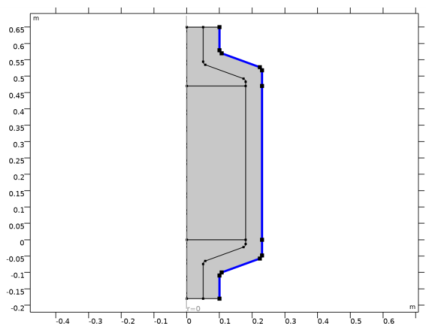
Click OK. Thus you created a selection for the inlet boundary as it will be used again during the model setup.
|
|
1
|
|
3
|
|
4
|
|
5
|
|
6
|
Click OK. Thus a selection for the outlet boundary was created as it will be used again during the model setup.
|
|
1
|
|
2
|
|
3
|
|
4
|
|
1
|
|
2
|
|
3
|
|
1
|
|
2
|
|
3
|
|
4
|
|
1
|
|
2
|
|
3
|
|
4
|
|
5
|
|
1
|
|
2
|
|
3
|
|
4
|
|
1
|
|
2
|
|
1
|
|
2
|
|
3
|
|
4
|
|
1
|
|
2
|
|
3
|
|
4
|
|
1
|
|
2
|
|
3
|
|
4
|
|
5
|
|
6
|
|
7
|
|
1
|
|
2
|
|
3
|
|
4
|
|
1
|
|
1
|
|
2
|
|
1
|
In the Model Builder window, under Study 1>Solver Configurations>Solution 1 (sol1) right-click Time-Dependent Solver 1 and choose Stop Condition.
|
|
2
|
|
3
|
Click
|
|
5
|
|
6
|
|
1
|
|
2
|
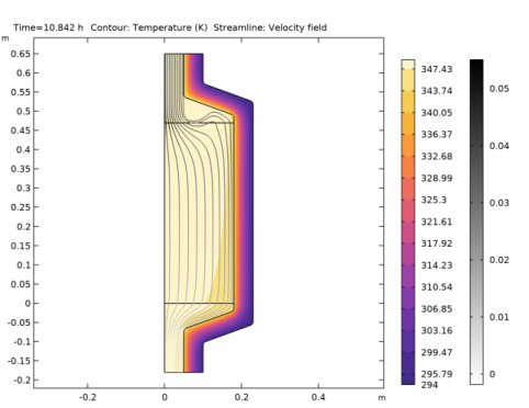
In the Settings window for 2D Plot Group, type Isothermal Contours & Velocity Streamlines in the Label text field.
|
|
1
|
In the Model Builder window, expand the Isothermal Contours & Velocity Streamlines node, then click Contour.
|
|
2
|
|
3
|
|
4
|
|
1
|
|
2
|
|
3
|
|
1
|
|
2
|
|
3
|
|
4
|
|
5
|
|
1
|
|
2
|
|
3
|
|
4
|
|
1
|
|
2
|
|
3
|
|
4
|
Locate the Expressions section. In the table, enter the following settings:
|
|
5
|
Click
|
|
1
|
Go to the Table window.
|
|
2
|
|
1
|
|
2
|
|
3
|
|
4
|
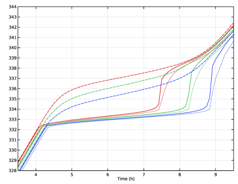
In the Columns list, choose Paraffin temperature (K), Point: (0, 0.05), Paraffin temperature (K), Point: (0, 0.235), and Paraffin temperature (K), Point: (0, 0.42).
|
|
5
|
Locate the Coloring and Style section. Find the Line style subsection. From the Line list, choose Dotted.
|
|
1
|
|
2
|
|
3
|
In the Columns list, choose Water temperature (K), Point: (0, 0.05), Water temperature (K), Point: (0, 0.235), and Water temperature (K), Point: (0, 0.42).
|
|
4
|
Locate the Coloring and Style section. Find the Line style subsection. From the Line list, choose Dashed.
|
|
5
|
|
1
|
Locate the Data section. In the Columns list, choose Porous Medium temperature (K), Point: (0, 0.05), Porous Medium temperature (K), Point: (0, 0.235), and Porous Medium temperature (K), Point: (0, 0.42).
|
|
2
|
|
1
|
|
2
|
|
3
|
|
4
|
|
5
|
|
6
|
|
7
|
|
8
|
|
1
|
|
2
|
|
3
|
|
1
|
|
2
|
|
3
|
|
1
|
|
2
|
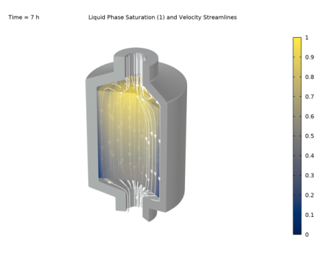
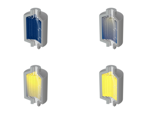
In the Settings window for Volume, click Replace Expression in the upper-right corner of the Expression section. From the menu, choose Component 1 (comp1)>Heat Transfer in Solids and Fluids>Phase change>ht.theta2 - Phase indicator, phase 2.
|
|
3
|
|
4
|
|
5
|
|
1
|
|
2
|
|
3
|
|
1
|
|
2
|
|
3
|
|
4
|
|
1
|
|
2
|
|
3
|
|
4
|
|
1
|
|
2
|
|
3
|
|
4
|
Locate the Coloring and Style section. Find the Point style subsection. From the Type list, choose Arrow.
|
|
5
|
|
7
|
|
1
|
|
2
|
|
3
|
|
4
|
|
5
|
|
6
|
|
7
|
|
8
|
|
9
|
|
10
|
|
11
|