PDF

1D Lithium-Ion Battery Model Charge Control
Introduction
Charge controllers are useful to improve battery lifetime as they prevent overcharging and possible overvoltage. This model combines the electrochemistry simulation in COMSOL Multiphysics with a control system implemented in Simulink. The control system adjusts the electric current during the charge phase to prevent overvoltage. The electric current is also controlled in the discharge phase to ensure constant power.
Note: This models requires licenses for both the Battery Design Module and LiveLink™ for Simulink®.
Model Definition
The simulation consists of controlling the current in a lithium-ion battery in different cases. In charging mode, the voltage is limited to a maximum value of 4.1 V. In use, the battery is requested to provide a constant power of 5 W. When the voltage reaches a minimum value of 3 V, the current is cut to prevent possible battery damage.
The control system diagram is implemented in Simulink, while the battery’s electrochemical model is computed in COMSOL Multiphysics. Both programs can run together by means of a COMSOL Cosimulation block in the simulation diagram.
The battery cell model is created using the Lithium-Ion Battery interface in COMSOL Multiphysics. A more detailed description on how to set up this type of model can be found in the model example 1D Lithium-Ion Battery Model for the Capacity Fade Tutorial in the Battery Design Module Application Library.
The cosimulation with COMSOL Multiphysics and Simulink is set up by exporting a COMSOL Cosimulation file from the COMSOL model, and then adding this to the COMSOL Cosimulation block in the Simulink simulation diagram. The input of the block consists in the applied current, provided by Simulink. The block output is the cell voltage.
Figure 1 below shows the controller diagram implementation in Simulink for both charging and discharging phase.
Figure 1: Charge/discharge control diagram of a battery cosimulation in Simulink.
Results and Discussion
Figure 2 shows the battery voltage variation during the charging and discharging phases. The voltage never exceeds 4.1 V.
Figure 2: Battery voltage during charge and discharge.
Figure 3 shows the current in the battery. At the beginning, a constant current of 1.6 A ensures maximal charging. Then, to prevent battery damage, the current is dropped to limit the voltage until full charge. During discharge, the current is adjusted to ensure a utility power of 5 W.
Figure 3: Battery current during charge and discharge.
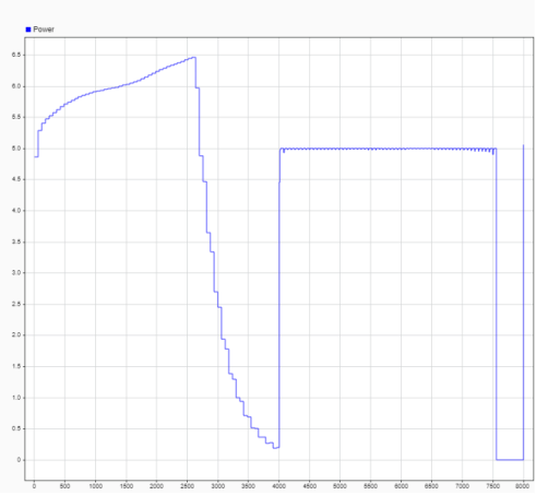
Figure 4 shows the battery power. You can notice the effect of the PI controller that ensure a constant utility power set to 5W.
Figure 4: Battery power during charge and discharge.
Setting Up the Cosimulation
Follow the workflow below to set up the cosimulation with COMSOL Multiphysics and Simulink:
1
2
3
4
5
6
Application Library path: LiveLink_for_Simulink/Tutorials/li_battery_llsimulink
Modeling Instructions — COMSOL Desktop
Start this tutorial by opening a seed file that contains a 1D battery model, without any capacity fade reactions or mechanisms added.
Application Libraries
1
From the File menu, choose Application Libraries.
2
In the Application Libraries window, select Battery Design Module>Batteries, Lithium-Ion>capacity_fade_seed in the tree.
3
Parameters 1
1
In the Model Builder window, under Global Definitions click Parameters 1.
2
In the Settings window for Parameters, locate the Parameters section.
3
4
Lithium-Ion Battery (liion)
1
In the Model Builder window, expand the Component 1 (comp1) node, then click Lithium-Ion Battery (liion).
2
In the Settings window for Lithium-Ion Battery, locate the Cross-Sectional Area section.
3
In the Ac text field, type Ac.
Initial Cell Charge Distribution 1
1
In the Model Builder window, expand the Lithium-Ion Battery (liion) node, then click Initial Cell Charge Distribution 1.
2
In the Settings window for Initial Cell Charge Distribution, locate the Battery Cell Parameters section.
3
In the Qcell,0 text field, type Q0*Ac.
Electrode Current 1
1
In the Physics toolbar, click  Boundaries and choose Electrode Current.
2
3
In the Settings window for Electrode Current, locate the Electrode Current section.
4
In the Is,total text field, type I.
5
In the φs,bnd,init text field, type E_min.
Definitions (comp1)
Integration 1 (intop1)
1
In the Definitions toolbar, click  Nonlocal Couplings and choose Integration.
2
In the Settings window for Integration, locate the Source Selection section.
3
From the Geometric entity level list, choose Boundary.
4
Variables 1
1
In the Model Builder window, click Variables 1.
2
In the Settings window for Variables, locate the Variables section.
3
>In the table, replace the settings for I_cell and E_cell with the following:
Study 1
Step 2: Time Dependent
1
In the Model Builder window, under Study 1 right-click Step 2: Time Dependent and choose Delete.
2
In the Home toolbar, click  Compute.
Add Study
1
In the Home toolbar, click  Add Study to open the Add Study window.
2
Go to the Add Study window.
3
Find the Studies subsection. In the Select Study tree, select General Studies>Time Dependent.
4
5
In the Home toolbar, click  Add Study to close the Add Study window.
Study 2
Step 1: Time Dependent
1
In the Settings window for Time Dependent, locate the Study Settings section.
2
In the Output times text field, type range(0,180,3800).
3
Click to expand the Values of Dependent Variables section. Find the Initial values of variables solved for subsection. From the Settings list, choose User controlled.
4
From the Method list, choose Solution.
5
From the Study list, choose Study 1, Current Distribution Initialization.
6
In the Study toolbar, click  Get Initial Value.
Save the COMSOL Model
1
From the File menu, choose Save As.
2
Browse to a suitable folder, enter the filename li_battery_llsimulink.mph, and then click Save.
Exporting the Cosimulation File
In the following configure the cosimulation, and export the file for cosimulation that will be loaded into Simulink.
Global Definitions
Cosimulation for Simulink 1
1
In the Study toolbar, click  Cosimulation for Simulink.
2
In the Settings window for Cosimulation for Simulink, locate the Filename section.
3
In the Filename text field, type li_battery_llsimulink.
4
Locate the Inputs section. Click  Add.
5
6
Locate the Outputs section. In the table, enter the following settings:
7
Locate the Study section. Find the Store solution subsection. Clear the According to study step settings check box.
8
Click  Export.
Modeling Instructions — Simulink
Once you have created the COMSOL model and saved the cosimulation file you can start Simulink to continue with the setup there.
1
2
In MATLAB enter the command mphapplicationlibraries to start the GUI for viewing models from the LiveLink for Simulink application library.
3
4
The included COMSOL Cosimulation block is already configured with a cosimulation file based on the model from the COMSOL Application Library and ready to run. If you want to run the simulation directly, go to Step 7 below. Else, if you want to use the model file and cosimulation file you have created by following the steps in the section Modeling Instructions — COMSOL Desktop, you can continue with Step 5 below.
5
6
Note: In case the folder path of the file for cosimulation for Simulink is not set in MATLAB enter the full filename.
For this simulation the stop time is set to 8,000 s and the communication step size is set to 60 s.
7