PDF

Isothermal MEMS Heat Exchanger
Introduction
The following example builds and solves a conduction and convection heat transfer problem using the Heat Transfer interface.
The example concerns a stainless-steel MEMS heat exchanger, which you can find in lab-on-a-chip devices in biotechnology and in microreactors such as for micro fuel cells. This application examines the heat exchanger in 3D, and it involves heat transfer through both convection and conduction.
Model Definition
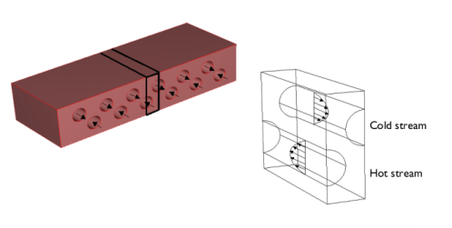
Figure 1 shows the geometry of the heat exchanger. It is necessary to model only one unit cell because they are all almost identical except for edge effects in the outer cells.
Figure 1: Depiction of the modeled part of the heat exchanger (left).
The governing equation for this model is the heat equation for conductive and convective heat transfer
where Cp denotes the specific heat capacity (SI unit: J/(kg·K)), T is the temperature (SI unit: K), k is the thermal conductivity (SI unit: W/(m·K)), ρ is the density (SI unit: kg/m3), u is the velocity vector (SI unit: m/s), and Q is a sink or source term (which you set to zero because there is no production or consumption of heat in the device).
In the solid part of the heat exchanger the velocity vector, u = (uvw), is set to zero in all directions. In the channels the velocity field is defined by an analytical expression that approximates fully-developed laminar flow for a circular cross section. For both the hot and cold streams, you set the velocity components in the x and z directions to zero.
For the hot stream, the expression
gives the y-component of the velocity where
vmax is the maximum velocity (SI unit: m/s), which arises in the middle of the channel
r is the distance from the center of the channel (SI unit: m)
R is the channel radius (SI unit: m)
You describe velocity in the cold stream in the same manner but in the opposite direction
In an extended approach, instead of using the analytical expression for the velocity field, the fluid in the channels can be simulated using the Laminar Flow interface. Here the density is defined as
where ρm is the mean density (SI unit: kg/m3), and Tm = (Tcold + Thot) ⁄ 2 is the mean fluid temperature.
The boundary conditions are insulating for all outer surfaces except for the inlet and outlet boundaries in the fluid channels. At the inlets, you specify constant temperatures for the cold and hot streams, Tcold and Thot, respectively. At the outlets, convection dominates the transport of heat so you apply the convective flux boundary condition:
Results and Discussion
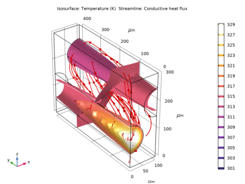
Figure 2 shows the temperature isosurfaces and the heat flux streamlines for the conductive heat flux in the device. The temperature isosurfaces clearly show the convective term’s influence in the channels. Figure 3 displays the corresponding results for the extended application (see Nonisothermal MEMS Heat Exchanger for model description and results). As the plot shows, the temperature distribution is very similar to that in the first study, which can therefore be concluded to be a good approximation of the extended case.
Figure 2: Isotherms and conductive heat flux streamlines in the cell unit’s geometry.
Figure 3: Extended application results; isotherms and conductive heat flux streamlines in the cell unit’s geometry.
Application Library path: Heat_Transfer_Module/Heat_Exchangers/heat_exchanger_iso
Modeling Instructions
From the File menu, choose New.
New
In the New window, click  Model Wizard.
Model Wizard
1
In the Model Wizard window, click  3D.
2
In the Select Physics tree, select Heat Transfer>Heat Transfer in Solids and Fluids (ht).
3
Click Add.
4
Click  Study.
5
In the Select Study tree, select General Studies>Stationary.
6
Global Definitions
Parameters 1
1
In the Model Builder window, under Global Definitions click Parameters 1.
2
In the Settings window for Parameters, locate the Parameters section.
3
Geometry 1
1
In the Model Builder window, under Component 1 (comp1) click Geometry 1.
2
In the Settings window for Geometry, locate the Units section.
3
From the Length unit list, choose µm.
Block 1 (blk1)
1
In the Geometry toolbar, click  Block.
2
In the Settings window for Block, locate the Size and Shape section.
3
In the Width text field, type 100.
4
In the Depth text field, type 400.
5
In the Height text field, type 300.
6
In the Geometry toolbar, click  Build All.
Cylinder 1 (cyl1)
1
In the Geometry toolbar, click  Cylinder.
2
In the Settings window for Cylinder, locate the Size and Shape section.
3
In the Radius text field, type R.
4
In the Height text field, type 400.
5
Locate the Position section. In the z text field, type 2*R.
6
Locate the Axis section. From the Axis type list, choose y-axis.
7
In the Geometry toolbar, click  Build All.
Copy 1 (copy1)
1
In the Geometry toolbar, click  Transforms and choose Copy.
2
3
In the Settings window for Copy, locate the Displacement section.
4
In the x text field, type 2*R.
5
In the z text field, type 2*R.
6
In the Geometry toolbar, click  Build All.
Compose 1 (co1)
1
In the Geometry toolbar, click  Booleans and Partitions and choose Compose.
2
Click in the Graphics window and then press Ctrl+A to select all objects.
3
In the Settings window for Compose, locate the Compose section.
4
In the Set formula text field, type blk1*(cyl1+copy1)+blk1.
5
In the Geometry toolbar, click  Build All.
Define some selections that will be useful during the model set-up.
Definitions
Solid
1
In the Definitions toolbar, click  Explicit.
2
In the Settings window for Explicit, type Solid in the Label text field.
3
Hot Channel
1
In the Definitions toolbar, click  Explicit.
2
In the Settings window for Explicit, type Hot Channel in the Label text field.
3
Cold Channel
1
In the Definitions toolbar, click  Explicit.
2
In the Settings window for Explicit, type Cold Channel in the Label text field.
3
Channels
1
In the Definitions toolbar, click  Union.
2
In the Settings window for Union, type Channels in the Label text field.
3
Locate the Input Entities section. Under Selections to add, click  Add.
4
In the Add dialog box, in the Selections to add list, choose Hot Channel and Cold Channel.
5
Channel Walls
1
In the Definitions toolbar, click  Adjacent.
2
In the Settings window for Adjacent, type Channel Walls in the Label text field.
3
Locate the Input Entities section. Under Input selections, click  Add.
4
In the Add dialog box, in the Input selections list, choose Solid and Channels.
5
6
In the Settings window for Adjacent, locate the Output Entities section.
7
Clear the Exterior boundaries check box.
8
Select the Interior boundaries check box.
Define two local variables for the radial component of a cylindrical coordinate system aligned with each channel. Later use them to define the laminar velocity profile.
Variables 1
1
In the Definitions toolbar, click  Local Variables.
2
In the Settings window for Variables, locate the Geometric Entity Selection section.
3
From the Geometric entity level list, choose Domain.
4
From the Selection list, choose Hot Channel.
5
Locate the Variables section. In the table, enter the following settings:
Variables 2
1
In the Definitions toolbar, click  Local Variables.
2
In the Settings window for Variables, locate the Geometric Entity Selection section.
3
From the Geometric entity level list, choose Domain.
4
5
From the Selection list, choose Cold Channel.
6
Locate the Variables section. In the table, enter the following settings:
Add Material
1
In the Home toolbar, click  Add Material to open the Add Material window.
2
Go to the Add Material window.
3
In the tree, select Built-in>Steel AISI 4340.
4
Click Add to Component in the window toolbar.
5
In the tree, select Built-in>Water, liquid.
6
Click Add to Component in the window toolbar.
7
In the Home toolbar, click  Add Material to close the Add Material window.
Materials
Steel AISI 4340 (mat1)
1
In the Model Builder window, under Component 1 (comp1)>Materials click Steel AISI 4340 (mat1).
2
In the Settings window for Material, locate the Geometric Entity Selection section.
3
From the Selection list, choose Solid.
Water, liquid (mat2)
1
In the Model Builder window, click Water, liquid (mat2).
2
In the Settings window for Material, locate the Geometric Entity Selection section.
3
From the Selection list, choose Channels.
Heat Transfer in Solids and Fluids (ht)
Fluid 1
1
In the Model Builder window, under Component 1 (comp1)>Heat Transfer in Solids and Fluids (ht) click Fluid 1.
2
In the Settings window for Fluid, locate the Domain Selection section.
3
From the Selection list, choose Hot Channel.
4
Locate the Heat Convection section. Specify the u vector as
5
Locate the Thermodynamics, Fluid section. From the Fluid type list, choose Gas/Liquid.
6
From the γ list, choose User defined.
Fluid 2
1
In the Physics toolbar, click  Domains and choose Fluid.
2
In the Settings window for Fluid, locate the Domain Selection section.
3
From the Selection list, choose Cold Channel.
4
Locate the Heat Convection section. Specify the u vector as
5
Locate the Thermodynamics, Fluid section. From the Fluid type list, choose Gas/Liquid.
6
From the γ list, choose User defined.
Inflow 1
1
In the Physics toolbar, click  Boundaries and choose Inflow.
2
3
In the Settings window for Inflow, locate the Upstream Properties section.
4
In the Tustr text field, type T_hot.
Inflow 2
1
In the Physics toolbar, click  Boundaries and choose Inflow.
2
3
In the Settings window for Inflow, locate the Upstream Properties section.
4
In the Tustr text field, type T_cold.
Outflow 1
1
In the Physics toolbar, click  Boundaries and choose Outflow.
2
Mesh 1
Free Triangular 1
1
In the Mesh toolbar, click  Boundary and choose Free Triangular.
2
In the Settings window for Free Triangular, locate the Boundary Selection section.
3
From the Selection list, choose Channel Walls.
Size 1
1
Right-click Free Triangular 1 and choose Size.
2
In the Settings window for Size, locate the Element Size section.
3
Click the Custom button.
4
Locate the Element Size Parameters section. Select the Maximum element size check box.
5
Free Tetrahedral 1
1
In the Mesh toolbar, click  Free Tetrahedral.
2
In the Model Builder window, right-click Mesh 1 and choose Build All.
Study 1
In the Home toolbar, click  Compute.
Results
Temperature (ht)
The first default plot shows the temperature.
Isothermal Contours (ht)
The second default plot shows isothermal contours. To reproduce the Figure 2, proceed as follows:
Isosurface
1
In the Model Builder window, expand the Isothermal Contours (ht) node, then click Isosurface.
2
In the Settings window for Isosurface, locate the Levels section.
3
From the Entry method list, choose Levels.
4
In the Levels text field, type range(301,2,329).
Isothermal Contours (ht)
In the Model Builder window, click Isothermal Contours (ht).
Streamline 1
1
In the Isothermal Contours (ht) toolbar, click  Streamline.
2
In the Settings window for Streamline, locate the Streamline Positioning section.
3
From the Positioning list, choose Starting-point controlled.
4
Locate the Coloring and Style section. Find the Line style subsection. From the Type list, choose Tube.
5
Select the Radius scale factor check box.
6
Find the Point style subsection. From the Type list, choose Arrow.
7
In the Isothermal Contours (ht) toolbar, click  Plot.