PDF

Solid Oxide Electrolyzer
Introduction
This example models a solid oxide electrolyzer cell wherein water vapor is reduced to form hydrogen gas on the cathode, and oxygen gas is evolved on the anode. The current distribution in the cell is coupled to the cathode mass transfer of hydrogen and water and momentum transport.
Model Definition
On the anode, oxygen ions are oxidized to form oxygen gas,
(1)
whereas on the cathode, water vapor is reduced to form hydrogen gas and oxygen ions:
(2)
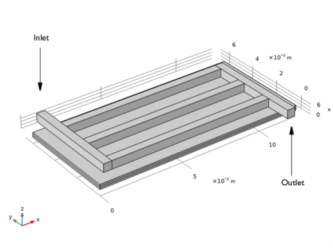
Figure 1 shows the model geometry. Since the oxygen is the only gas present in the anode gas chamber, and isobaric conditions are assumed, there is no need to explicitly model the anode gas transport. Four computational domains are hence used in the model: the cathode gas channels, the cathode gas diffusion electrode, the solid oxide electrolyte layer, and the anode gas diffusion electrode.
Figure 1: Model geometry. From top: Cathode gas channels, cathode gas diffusion electrode, solid oxide electrolyte layer, and anode gas diffusion layer. The positions of the inlet and outlet are indicated in the figure.
The composition of the hydrogen-water vapor mixture will change as a result of the electrochemical reactions. The mass transport of hydrogen and water vapor is modeled in the cathode gas channels and the gas diffusion electrode, coupled to the resulting (laminar) flow of the gas mixture.
The current distribution is defined assuming a constant conductivity of the solid electrolyte. The Water Electrolyzer interface is used to define the electrode reactions and the electrolyte charge transport in the porous gas diffusion electrodes and the electrolyte layer, as well as the mass transport of hydrogen and water. The momentum flow is defined in the model using the Free and Porous Media Flow interface. Brinkman equations are used for the porous gas diffusion electrodes and Navier-Stokes equations are used for the nonporous gas channels.
On the cathode side, the electrode kinetics depends on the local concentration of water and hydrogen according to the law of mass action (and Nernst equation). On the anode side, and a uniform partial pressure of oxygen is assumed and a concentration-independent Butler-Volmer expression is hence used to define the electrode kinetics.
The properties of the cathode gas mixture, as well as the equilibrium potentials of the electrode reactions are automatically defined by the default built-in options of the Water Electrolyzer interface.
Results and Discussion
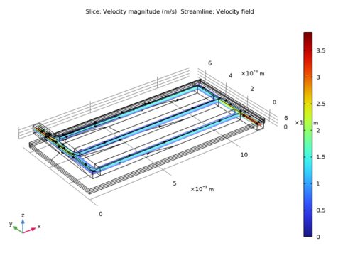
Figure 2 shows the velocity magnitude distribution in the cell. The highest velocities are located close to the inlet and outlet.
Figure 2: Velocity in the cell.
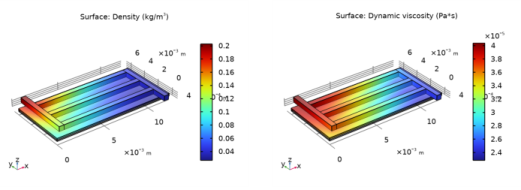
Figure 3 shows how the density and the dynamic viscosity of the gas relate to the hydrogen and water molar fractions shown in Figure 4. As the hydrogen content of the gas increases toward the outlet, the density and the viscosity both decrease.
Figure 3: Density (left) and dynamic viscosity (right).
Figure 4: Hydrogen (left) and water vapor (right) molar fractions.
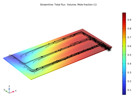
Figure 5 shows the molar fraction of hydrogen in the gas mixture, and the corresponding hydrogen flux streamlines. The molar fraction is close to zero at the inlet and almost 100% at the outlet.
Figure 5: Hydrogen molar fraction (slice) and flux (streamlines).
Finally, Figure 6 shows the cross-sectional electrolyte current density in the middle of the electrolyte between the anode and the cathode. The current density is highest close to the inlet, where the water/hydrogen ratio is high, and decreases toward the outlet.
Figure 6: Electrolyte current density through electrolyte layer.
Application Library path: Fuel_Cell_and_Electrolyzer_Module/Electrolyzers/soec
Modeling Instructions
This tutorial models the current distribution in a solid oxide electrolyzer. The tutorial comprises two major parts. First, a secondary (not concentration dependent) current distribution is modeled. In the second part, mass and momentum transport are added to model a concentration-dependent current distribution of the cell, where the mixture properties of the anode gas depends on the molar fractions of water and hydrogen.
From the File menu, choose New.
New
In the New window, click  Model Wizard.
Model Wizard
1
In the Model Wizard window, click  3D.
2
In the Select Physics tree, select Electrochemistry>Water Electrolyzers>Solid Oxide (we).
3
Click Add.
4
Click  Study.
5
In the Select Study tree, select Preset Studies for Selected Physics Interfaces>Stationary with Initialization.
6
Geometry 1
The model geometry is available as a parameterized geometry sequence in a separate MPH-file. If you want to build it from scratch, follow the instructions in the section Appendix - Geometry Modeling Instructions. Otherwise load it from file using the following steps.
1
In the Geometry toolbar, click Insert Sequence and choose Insert Sequence.
2
3
In the Geometry toolbar, click  Build All.
Global Definitions
Geometry Parameters
1
In the Model Builder window, under Global Definitions click Parameters 1.
2
In the Settings window for Parameters, type Geometry Parameters in the Label text field.
Physics Parameters
Some parameters were imported with the geometry sequence. Import some additional physics parameters from a text file.
1
In the Home toolbar, click  Parameters and choose Add>Parameters.
2
In the Settings window for Parameters, type Physics Parameters in the Label text field.
3
Locate the Parameters section. Click  Load from File.
4
Water Electrolyzer (we)
Now define the current distribution in the gas diffusion electrodes and the electrolyte.
1
In the Model Builder window, under Component 1 (comp1) click Water Electrolyzer (we).
2
In the Settings window for Water Electrolyzer, locate the Domain Selection section.
3
Click  Clear Selection.
4
5
Locate the H2 Gas Mixture section. Find the Transport mechanisms subsection. Clear the Include gas phase diffusion check box.
Membrane 1
1
In the Physics toolbar, click  Domains and choose Membrane.
2
Add Material
1
In the Home toolbar, click  Add Material to open the Add Material window.
2
Go to the Add Material window.
3
In the tree, select Fuel Cell and Electrolyzer>Solid Oxides>Yttria-Stabilized Zirconia, 8YSZ, (ZrO2)0.92-(Y2O3)0.08.
4
Right-click and choose Add to Component 1 (comp1).
5
In the Home toolbar, click  Add Material to close the Add Material window.
Water Electrolyzer (we)
Electrolyte Phase 1
In the Electrolyte Phase node, the electrolyte conductivity is set to be taken from the Materials node.
H2 Gas Diffusion Electrode 1
Set up the properties of the H2 Gas Diffusion Electrode node. The details of electrode kinetics are set in the child node. Note that the reference equilibrium potential is calculated automatically when the default Built in option is used.
1
In the Physics toolbar, click  Domains and choose H2 Gas Diffusion Electrode.
2
In the Settings window for H2 Gas Diffusion Electrode, locate the Domain Selection section.
3
From the Selection list, choose Cathode.
4
Locate the Electrode Charge Transport section. In the σs text field, type sigmaeff_s.
5
Locate the Effective Electrolyte Charge Transport section. In the εl text field, type por_l.
H2 Gas Diffusion Electrode Reaction 1
1
In the Model Builder window, click H2 Gas Diffusion Electrode Reaction 1.
2
In the Settings window for H2 Gas Diffusion Electrode Reaction, locate the Electrode Kinetics section.
3
In the i0,ref(T) text field, type i0_H2.
4
Locate the Active Specific Surface Area section. In the av text field, type S.
O2 Gas Diffusion Electrode 1
Similarly, set up the properties of the O2 Gas Diffusion Electrode node. The details of electrode kinetics are set in the child node. Note that the reference equilibrium potential is calculated automatically when the default Built in option is used.
1
In the Physics toolbar, click  Domains and choose O2 Gas Diffusion Electrode.
2
In the Settings window for O2 Gas Diffusion Electrode, locate the Domain Selection section.
3
From the Selection list, choose Anode.
4
Locate the Electrode Charge Transport section. In the σs text field, type sigmaeff_s.
5
Locate the Effective Electrolyte Charge Transport section. In the εl text field, type por_l.
O2 Gas Diffusion Electrode Reaction 1
1
In the Model Builder window, click O2 Gas Diffusion Electrode Reaction 1.
2
In the Settings window for O2 Gas Diffusion Electrode Reaction, locate the Electrode Kinetics section.
3
In the i0,ref(T) text field, type i0_O2.
4
In the αa text field, type 3.5.
5
Locate the Active Specific Surface Area section. In the av text field, type S.
Electronic Conducting Phase 1
Finally, set up the boundary conditions.
1
In the Model Builder window, under Component 1 (comp1)>Water Electrolyzer (we) click Electronic Conducting Phase 1.
Electric Ground 1
1
In the Physics toolbar, click  Attributes and choose Electric Ground.
2
In the Settings window for Electric Ground, locate the Boundary Selection section.
3
From the Selection list, choose Cathode Current Collector.
Electronic Conducting Phase 1
In the Model Builder window, click Electronic Conducting Phase 1.
Electrode Current 1
1
In the Physics toolbar, click  Attributes and choose Electrode Current.
2
In the Settings window for Electrode Current, locate the Electrode Current section.
3
From the list, choose Average current density.
4
Locate the Boundary Selection section. From the Selection list, choose Anode Current Collector.
5
Locate the Electrode Current section. In the is,average text field, type I_avg.
Global Definitions
Default Model Inputs
Default Model Inputs node can be used to set the Temperature for the entire model. This node may be accessed by multiple physics nodes.
1
In the Model Builder window, under Global Definitions click Default Model Inputs.
2
In the Settings window for Default Model Inputs, locate the Browse Model Inputs section.
3
In the tree, select General>Temperature (K) - minput.T.
4
Find the Expression for remaining selection subsection. In the Temperature text field, type T.
Mesh 1
The physics settings for the first part of the tutorial are now complete. Add a user-defined mesh.
Size 1
1
In the Model Builder window, under Component 1 (comp1) right-click Mesh 1 and choose Size.
2
In the Settings window for Size, click to expand the Element Size Parameters section.
3
Locate the Element Size section. Click the Custom button.
4
Locate the Element Size Parameters section. Select the Maximum element size check box.
5
Swept 1
1
In the Mesh toolbar, click  Swept.
2
In the Settings window for Swept, locate the Domain Selection section.
3
From the Geometric entity level list, choose Domain.
4
5
Click  Build Selected.
Boundary Layers 1
Also add boundary layer mesh nodes at this stage. These are actually not needed for the first calculation, but will improve the accuracy and convergence of the solution for the second part of the tutorial when mass transport and convection has been added.
1
In the Mesh toolbar, click  Boundary Layers.
2
In the Settings window for Boundary Layers, locate the Geometric Entity Selection section.
3
From the Geometric entity level list, choose Domain.
4
Boundary Layer Properties
1
In the Model Builder window, click Boundary Layer Properties.
2
In the Settings window for Boundary Layer Properties, locate the Boundary Selection section.
3
Click  Paste Selection.
4
In the Paste Selection dialog box, type 21-23, 25, 28-30, 32, 35-37, 39 in the Selection text field.
5
6
In the Settings window for Boundary Layer Properties, locate the Layers section.
7
In the Number of layers text field, type 2.
8
In the Stretching factor text field, type 1.3.
9
From the Thickness specification list, choose First layer.
10
In the Thickness text field, type H_ch/10.
11
Click  Build Selected.
Free Tetrahedral 1
1
In the Mesh toolbar, click  Free Tetrahedral.
2
In the Settings window for Free Tetrahedral, locate the Domain Selection section.
3
From the Geometric entity level list, choose Domain.
4
5
Click  Build Selected.
Boundary Layers 2
1
In the Model Builder window, under Component 1 (comp1)>Mesh 1 right-click Boundary Layers 1 and choose Duplicate.
2
In the Settings window for Boundary Layers, locate the Geometric Entity Selection section.
3
Click  Clear Selection.
4
Boundary Layer Properties
1
In the Model Builder window, expand the Boundary Layers 2 node, then click Boundary Layer Properties.
2
In the Settings window for Boundary Layer Properties, locate the Boundary Selection section.
3
Click  Clear Selection.
4
Click  Paste Selection.
5
In the Paste Selection dialog box, type 14-18, 24, 31, 38, 41, 43-45, 47, 49, 51, 52 in the Selection text field.
6
Boundary Layers 2
In the Model Builder window, right-click Boundary Layers 2 and choose Build Selected.
Free Triangular 1
1
In the Mesh toolbar, click  Boundary and choose Free Triangular.
2
In the Settings window for Free Triangular, locate the Boundary Selection section.
3
From the Selection list, choose Cathode Current Collector.
4
Click  Build Selected.
Swept 2
In the Mesh toolbar, click  Swept.
Distribution 1
1
Right-click Swept 2 and choose Distribution.
2
In the Settings window for Distribution, locate the Domain Selection section.
3
Click  Clear Selection.
4
5
Locate the Distribution section. From the Distribution type list, choose Predefined.
6
In the Element ratio text field, type 2.
7
Select the Reverse direction check box.
Distribution 2
1
In the Model Builder window, right-click Swept 2 and choose Distribution.
2
In the Settings window for Distribution, locate the Domain Selection section.
3
Click  Clear Selection.
4
5
Locate the Distribution section. In the Number of elements text field, type 2.
Distribution 3
1
In the Model Builder window, under Component 1 (comp1)>Mesh 1>Swept 2 right-click Distribution 1 and choose Duplicate.
2
In the Settings window for Distribution, locate the Domain Selection section.
3
Click  Clear Selection.
4
5
Locate the Distribution section. Clear the Reverse direction check box.
6
Click  Build All.
Study 1
The problem is now ready for solving.
1
In the Home toolbar, click  Compute.
Results
Electrode Potential with Respect to Ground (we)
1
In the Electrode Potential with Respect to Ground (we) toolbar, click  Plot.
Inspect the potential plot. The plot should look as follows:
Component 1 (comp1)
Now start with the second part of the tutorial which adds a Free and Porous Media Flow interface to the cathode side of the model, enables hydrogen gas phase diffusion in the Water Electrolyzer interface, and couples the distribution of hydrogen and water vapor to the electrochemistry.
Add Physics
1
In the Home toolbar, click  Add Physics to open the Add Physics window.
2
Go to the Add Physics window.
3
In the tree, select Fluid Flow>Porous Media and Subsurface Flow>Free and Porous Media Flow (fp).
4
Click Add to Component 1 in the window toolbar.
5
In the Home toolbar, click  Add Physics to close the Add Physics window.
Free and Porous Media Flow (fp)
1
2
In the Settings window for Free and Porous Media Flow, locate the Domain Selection section.
3
Click  Create Selection.
4
In the Create Selection dialog box, type Gas domains in the Selection name text field.
5
6
In the Settings window for Free and Porous Media Flow, locate the Physical Model section.
7
From the Compressibility list, choose Compressible flow (Ma<0.3).
Porous Medium 1
1
Right-click Component 1 (comp1)>Free and Porous Media Flow (fp) and choose Porous Medium.
2
In the Settings window for Porous Medium, locate the Domain Selection section.
3
From the Selection list, choose Cathode.
Porous Matrix 1
1
In the Model Builder window, click Porous Matrix 1.
2
In the Settings window for Porous Matrix, locate the Matrix Properties section.
3
From the εp list, choose User defined. In the associated text field, type por.
4
From the κ list, choose User defined. In the associated text field, type kappa.
Inlet 1
1
In the Physics toolbar, click  Boundaries and choose Inlet.
2
In the Settings window for Inlet, locate the Boundary Selection section.
3
From the Selection list, choose Inlet.
4
Locate the Boundary Condition section. From the list, choose Mass flow.
5
Locate the Mass Flow section. In the m text field, type Mflux_in.
Outlet 1
1
In the Physics toolbar, click  Boundaries and choose Outlet.
2
In the Settings window for Outlet, locate the Boundary Selection section.
3
From the Selection list, choose Outlet.
4
Locate the Pressure Conditions section. Select the Normal flow check box.
Multiphysics
Reacting Flow, H2 Gas Phase 1 (rfh1)
In the Physics toolbar, click  Multiphysics Couplings and choose Domain>Reacting Flow, H2 Gas Phase.
Water Electrolyzer (we)
1
In the Model Builder window, under Component 1 (comp1) click Water Electrolyzer (we).
2
In the Settings window for Water Electrolyzer, locate the Domain Selection section.
3
From the Selection list, choose All domains.
4
Locate the H2 Gas Mixture section. Find the Transport mechanisms subsection. Select the Include gas phase diffusion check box.
H2 Gas Flow Channel 1
1
In the Physics toolbar, click  Domains and choose H2 Gas Flow Channel.
2
In the Settings window for H2 Gas Flow Channel, locate the Domain Selection section.
3
From the Selection list, choose Channel Domains.
H2 Gas Diffusion Electrode 1
1
In the Model Builder window, click H2 Gas Diffusion Electrode 1.
2
In the Settings window for H2 Gas Diffusion Electrode, locate the Gas Transport section.
3
In the εg text field, type por.
H2 Gas Phase 1
Note that the settings on the H2 Gas Phase node are either the default option or automatically set by the multiphysics coupling node. Set up the required boundary conditions and initial values.
1
In the Model Builder window, click H2 Gas Phase 1.
H2 Inlet 1
1
In the Physics toolbar, click  Attributes and choose H2 Inlet.
2
In the Settings window for H2 Inlet, locate the Boundary Selection section.
3
From the Selection list, choose Inlet.
4
Locate the Mixture Specification section. From the list, choose Mass flow rates.
5
In the J0,H2O text field, type Mflux_in.
H2 Gas Phase 1
In the Model Builder window, click H2 Gas Phase 1.
H2 Outlet 1
1
In the Physics toolbar, click  Attributes and choose H2 Outlet.
2
In the Settings window for H2 Outlet, locate the Boundary Selection section.
3
From the Selection list, choose Outlet.
Initial Values 1
1
In the Model Builder window, click Initial Values 1.
2
In the Settings window for Initial Values, locate the Initial Composition section.
3
In the x0,H2O text field, type 0.95*(1-x/(W_cell*stoich)).
Study 1
The concentration-dependent model is now ready for solving. Use a sequence of study steps, solving first for the current distribution initialization, then the flow, and finally the fully coupled problem. By solving for only one set of physics at a time in individual steps, suitable initial values automatically propagate to the final study step where the complete problem is solved.
Step 1: Current Distribution Initialization
1
In the Model Builder window, under Study 1 click Step 1: Current Distribution Initialization.
2
In the Settings window for Current Distribution Initialization, locate the Physics and Variables Selection section.
3
In the table, clear the Solve for check box for Reacting Flow, H2 Gas Phase 1 (rfh1).
Step 2: Stationary
1
In the Model Builder window, click Step 2: Stationary.
2
In the Settings window for Stationary, locate the Physics and Variables Selection section.
3
In the table, clear the Solve for check box for Water Electrolyzer (we).
4
In the table, clear the Solve for check box for Reacting Flow, H2 Gas Phase 1 (rfh1).
Stationary 2
1
In the Study toolbar, click  Study Steps and choose Stationary>Stationary.
Remove the old study sequence and generate a new one.
Solver Configurations
In the Model Builder window, under Study 1 right-click Solver Configurations and choose Delete Configurations.
Solution 1 (sol1)
1
In the Study toolbar, click  Show Default Solver.
2
In the Model Builder window, expand the Solution 1 (sol1) node.
3
In the Model Builder window, expand the Study 1>Solver Configurations>Solution 1 (sol1)>Stationary Solver 3 node.
4
Right-click Stationary Solver 3 and choose Fully Coupled.
5
In the Study toolbar, click  Compute.
The problem should solve in about two minutes.
Results
Start the postprocessing of the solution by inspecting and polishing the default plot for the velocity field.
Slice
1
In the Model Builder window, expand the Results>Velocity (fp) node, then click Slice.
2
In the Settings window for Slice, locate the Plane Data section.
3
From the Plane list, choose xy-planes.
4
From the Entry method list, choose Coordinates.
5
In the z-coordinates text field, type H_cell-H_ch/2.
6
In the Velocity (fp) toolbar, click  Plot.
Streamline 1
1
In the Model Builder window, right-click Velocity (fp) and choose Streamline.
2
In the Settings window for Streamline, click Replace Expression in the upper-right corner of the Expression section. From the menu, choose Component 1 (comp1)>Free and Porous Media Flow>Velocity and pressure>u,v,w - Velocity field.
3
Locate the Selection section. From the Selection list, choose Inlet.
4
Locate the Coloring and Style section. Find the Point style subsection. From the Type list, choose Arrow.
5
From the Arrow distribution list, choose Equal inverse time.
6
From the Color list, choose Black.
7
In the Velocity (fp) toolbar, click  Plot.
Density
The density of the gas mixture will change as water is replaced by hydrogen in the gas stream. Plot the density as follows:
1
In the Home toolbar, click  Add Plot Group and choose 3D Plot Group.
2
In the Settings window for 3D Plot Group, type Density in the Label text field.
Surface 1
1
Right-click Density and choose Surface.
2
In the Settings window for Surface, click Replace Expression in the upper-right corner of the Expression section. From the menu, choose Component 1 (comp1)>Free and Porous Media Flow>Material properties>fp.rho - Density - kg/m³.
3
In the Density toolbar, click  Plot.
Viscocity
Also the viscocity will change in the gas stream.
1
In the Home toolbar, click  Add Plot Group and choose 3D Plot Group.
2
In the Settings window for 3D Plot Group, type Viscocity in the Label text field.
Surface 1
1
Right-click Viscocity and choose Surface.
2
In the Settings window for Surface, click Replace Expression in the upper-right corner of the Expression section. From the menu, choose Component 1 (comp1)>Free and Porous Media Flow>Material properties>fp.mu - Dynamic viscosity - Pa·s.
3
In the Viscocity toolbar, click  Plot.
Mole Fraction, H2, Surface (we)
Default plots are created for the hydrogen and water molar fractions.
Mole Fraction, H2O, Surface (we)
Molar Fraction and Flux, H2
Create a plot for the hydrogen molar fraction and flux as follows:
1
In the Home toolbar, click  Add Plot Group and choose 3D Plot Group.
2
In the Settings window for 3D Plot Group, type Molar Fraction and Flux, H2 in the Label text field.
3
Locate the Plot Settings section. Clear the Plot dataset edges check box.
Streamline 1
1
Right-click Molar Fraction and Flux, H2 and choose Streamline.
2
In the Settings window for Streamline, click Replace Expression in the upper-right corner of the Expression section. From the menu, choose Component 1 (comp1)>Water Electrolyzer>Species H2>we.tfluxH2x,...,we.tfluxH2z - Total flux.
3
Locate the Streamline Positioning section. In the Number text field, type 30.
4
Locate the Selection section. From the Selection list, choose Outlet.
5
Locate the Coloring and Style section. Find the Point style subsection. From the Type list, choose Arrow.
6
From the Arrow distribution list, choose Equal inverse time.
7
From the Color list, choose Black.
Selection 1
1
Right-click Streamline 1 and choose Selection.
2
In the Settings window for Selection, locate the Selection section.
3
From the Selection list, choose Channel Domains.
Volume 1
1
In the Model Builder window, right-click Molar Fraction and Flux, H2 and choose Volume.
2
In the Settings window for Volume, click Replace Expression in the upper-right corner of the Expression section. From the menu, choose Component 1 (comp1)>Water Electrolyzer>Species H2>we.xH2 - Mole fraction.
Selection 1
1
Right-click Volume 1 and choose Selection.
2
In the Settings window for Selection, locate the Selection section.
3
From the Selection list, choose Cathode.
4
Click the  Show Grid button in the Graphics toolbar.
5
In the Molar Fraction and Flux, H2 toolbar, click  Plot.
Cross-Sectional Electrolyte Current Density
Finally, plot the current distribution across the electrolyte layer as follows:
1
In the Home toolbar, click  Add Plot Group and choose 3D Plot Group.
2
In the Settings window for 3D Plot Group, type Cross-Sectional Electrolyte Current Density in the Label text field.
3
Locate the Plot Settings section. Clear the Plot dataset edges check box.
Slice 1
1
Right-click Cross-Sectional Electrolyte Current Density and choose Slice.
2
In the Settings window for Slice, click Replace Expression in the upper-right corner of the Expression section. From the menu, choose Component 1 (comp1)>Water Electrolyzer>Electrolyte current density vector - A/m²>we.Ilz - Electrolyte current density vector, z component.
3
Locate the Plane Data section. From the Plane list, choose xy-planes.
4
From the Entry method list, choose Coordinates.
5
In the z-coordinates text field, type H_gde+H_el/2.
6
In the Cross-Sectional Electrolyte Current Density toolbar, click  Plot.
Appendix - Geometry Modeling Instructions
From the File menu, choose New.
New
In the New window, click  Model Wizard.
Model Wizard
1
In the Model Wizard window, click  3D.
2
Global Definitions
Geometry Parameters
1
In the Model Builder window, under Global Definitions click Parameters 1.
2
In the Settings window for Parameters, type Geometry Parameters in the Label text field.
3
Locate the Parameters section. Click  Load from File.
4
Geometry 1
Anode
1
In the Geometry toolbar, click  Block.
2
In the Settings window for Block, type Anode in the Label text field.
3
Locate the Size and Shape section. In the Width text field, type W_cell.
4
In the Depth text field, type D_cell.
5
In the Height text field, type H_gde.
6
Locate the Selections of Resulting Entities section. Select the Resulting objects selection check box.
Electrolyte
1
Right-click Anode and choose Duplicate.
2
In the Settings window for Block, type Electrolyte in the Label text field.
3
Locate the Position section. In the z text field, type H_gde.
Cathode
1
Right-click Electrolyte and choose Duplicate.
2
In the Settings window for Block, type Cathode in the Label text field.
3
Locate the Position section. In the z text field, type H_gde+H_el.
Work Plane 1 (wp1)
1
In the Geometry toolbar, click  Work Plane.
2
In the Settings window for Work Plane, locate the Plane Definition section.
3
In the z-coordinate text field, type H_cell-H_ch.
Work Plane 1 (wp1)>Plane Geometry
In the Model Builder window, click Plane Geometry.
Work Plane 1 (wp1)>Rectangle 1 (r1)
1
In the Work Plane toolbar, click  Rectangle.
2
In the Settings window for Rectangle, locate the Size and Shape section.
3
In the Width text field, type W_ch.
4
In the Height text field, type N_ch*(W_ch+W_rib).
5
Locate the Position section. In the xw text field, type W_rib/2.
6
In the yw text field, type W_rib/2.
Work Plane 1 (wp1)>Rectangle 2 (r2)
1
Right-click Component 1 (comp1)>Geometry 1>Work Plane 1 (wp1)>Plane Geometry>Rectangle 1 (r1) and choose Duplicate.
2
In the Settings window for Rectangle, locate the Position section.
3
In the xw text field, type W_rib/2+L_ch+W_ch.
4
In the yw text field, type -W_rib/2.
Work Plane 1 (wp1)>Rectangle 3 (r3)
1
In the Work Plane toolbar, click  Rectangle.
2
In the Settings window for Rectangle, locate the Size and Shape section.
3
In the Width text field, type L_ch.
4
In the Height text field, type W_ch.
5
Locate the Position section. In the xw text field, type W_rib/2+W_ch.
6
In the yw text field, type W_rib/2.
Work Plane 1 (wp1)>Array 1 (arr1)
1
In the Work Plane toolbar, click  Transforms and choose Array.
2
3
In the Settings window for Array, locate the Size section.
4
In the yw size text field, type N_ch.
5
Locate the Displacement section. In the yw text field, type W_ch+W_rib.
6
In the Work Plane toolbar, click  Build All.
Channel Domains
1
In the Model Builder window, right-click Geometry 1 and choose Extrude.
2
In the Settings window for Extrude, type Channel Domains in the Label text field.
3
Locate the Distances section. In the table, enter the following settings:
4
Locate the Selections of Resulting Entities section. Select the Resulting objects selection check box.
Form Union (fin)
In the Model Builder window, right-click Form Union (fin) and choose Build Selected.
Inlet
1
In the Geometry toolbar, click  Selections and choose Explicit Selection.
2
In the Settings window for Explicit Selection, type Inlet in the Label text field.
3
Locate the Entities to Select section. From the Geometric entity level list, choose Boundary.
4
On the object fin, select Boundary 19 only.
Outlet
1
In the Geometry toolbar, click  Selections and choose Explicit Selection.
2
In the Settings window for Explicit Selection, type Outlet in the Label text field.
3
Locate the Entities to Select section. From the Geometric entity level list, choose Boundary.
4
On the object fin, select Boundary 42 only.
Cathode Current Collector
1
In the Geometry toolbar, click  Selections and choose Explicit Selection.
2
In the Settings window for Explicit Selection, type Cathode Current Collector in the Label text field.
3
Locate the Entities to Select section. From the Geometric entity level list, choose Boundary.
4
On the object fin, select Boundaries 10, 26, 33, and 40 only.
Anode Current Collector
1
In the Geometry toolbar, click  Selections and choose Explicit Selection.
2
In the Settings window for Explicit Selection, type Anode Current Collector in the Label text field.
3
Locate the Entities to Select section. From the Geometric entity level list, choose Boundary.
4
On the object fin, select Boundary 3 only.