
|
|
|
|
•
|
To model composites you can use two approaches: You can use either the Layered Shell interface, that uses the layerwise theory, or the Layered Linear Elastic Material node in the Shell interface, that uses the Equivalent Single Layer (ESL) theory.
|
|
•
|
The multiple model method combines the aforementioned modeling approaches, and in order to combine the Layered Shell and Shell interfaces in the thickness direction, a Layered Shell-Shell Connection multiphyics coupling must be used. You must also use the Layered Material Stack node for the through-thickness coupling between the interfaces.
|
|
•
|
In a situation where Layered Shell and Shell interfaces are coupled in-plane, you must use a Layered Shell-Structural Transition multiphysics coupling. Here, the same Single Layer Material, Layered Material Link or Layered Material Stack node must be used in both interfaces. This modeling approach is also a multiple model method.
|
|
•
|
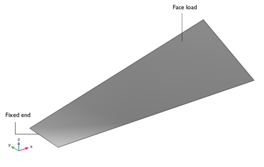
It is not advised to use the Layered Shell interface for discontinuous layers, as it can create problems in foldline constraints. No foldlines exist in the present model, however, so the Layered Shell interface can be used to model the PVC foam and the carbon-epoxy layers.
|
|
1
|
|
2
|
|
3
|
Click Add.
|
|
4
|
|
5
|
Click Add.
|
|
6
|
Click
|
|
7
|
|
8
|
Click
|
|
1
|
|
2
|
|
1
|
In the Model Builder window, under Global Definitions right-click Materials and choose Blank Material.
|
|
2
|
|
1
|
|
2
|
|
3
|
|
1
|
|
2
|
|
1
|
|
2
|
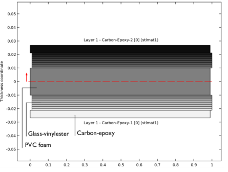
In the Settings window for Layered Material, type Layered Material: GV-[0/45/-45/90]_s in the Label text field.
|
|
3
|
|
4
|
Click
|
|
6
|
Click to expand the Preview Plot Settings section. In the Thickness-to-width ratio text field, type 0.6.
|
|
7
|
Locate the Layer Definition section. Click Layer Stack Preview in the upper-right corner of the section.
|
|
1
|
|
2
|
|
1
|
|
2
|
|
3
|
|
1
|
|
2
|
|
3
|
|
1
|
|
2
|
|
3
|
|
4
|
|
5
|
|
1
|
|
2
|
|
4
|
|
5
|
Click to expand the Scales section. In the table, enter the following settings:
|
|
6
|
|
7
|
|
8
|
|
9
|
|
1
|
In the Model Builder window, expand the Component 1 (comp1)>Definitions node, then click Boundary System 1 (sys1).
|
|
2
|
|
3
|
|
1
|
|
2
|
In the Settings window for Layered Material Link, type Glass-Vinylester-1 [0/45/-45/90]_s in the Label text field.
|
|
3
|
Locate the Link Settings section. From the Material list, choose Layered Material: GV-[0/45/-45/90]_s (lmat2).
|
|
1
|
|
2
|
|
3
|
|
1
|
|
2
|
In the Settings window for Layered Material Link, type Glass-Vinylester-2 [0/45/-45/90]_s in the Label text field.
|
|
3
|
Locate the Link Settings section. From the Material list, choose Layered Material: GV-[0/45/-45/90]_s (lmat2).
|
|
1
|
|
2
|
|
3
|
|
1
|
|
2
|
In the Settings window for Layered Material Stack, click to expand the Preview Plot Settings section.
|
|
3
|
|
4
|
|
5
|
|
1
|
|
2
|
In the Settings window for Layered Shell, type Layered Shell (Multiple Model Method) in the Label text field.
|
|
3
|
|
4
|
|
5
|
In the Selection table, select the check boxes for Layer 1 - Carbon-Epoxy-1 [0], Layer 1 - PVC Foam [0], and Layer 1 - Carbon-Epoxy-2 [0].
|
|
1
|
|
3
|
|
4
|
|
1
|
|
2
|
|
4
|
|
5
|
|
1
|
|
2
|
|
3
|
|
1
|
|
2
|
|
3
|
|
4
|
In the Show More Options dialog box, in the tree, select the check box for the node Physics>Advanced Physics Options.
|
|
5
|
Click OK.
|
|
6
|
|
7
|
|
1
|
|
3
|
|
4
|
|
5
|
|
6
|
|
7
|
|
1
|
|
3
|
|
1
|
|
2
|
|
3
|
|
1
|
In the Model Builder window, expand the Component 1 (comp1)>Shell 2 (Multiple Model Method) (shell2) node, then click Layered Linear Elastic Material 1.
|
|
2
|
|
3
|
|
1
|
In the Model Builder window, under Global Definitions>Materials click Material: Carbon-Epoxy (mat1).
|
|
2
|
|
1
|
|
2
|
|
1
|
|
2
|
|
1
|
|
2
|
|
3
|
|
1
|
|
2
|
|
3
|
|
1
|
|
2
|
|
3
|
|
1
|
|
2
|
|
3
|
|
4
|
|
1
|
|
2
|
In the Settings window for Study, type Study: Eigenfrequency (Multiple Model Method) in the Label text field.
|
|
3
|
|
4
|
|
1
|
|
2
|
|
1
|
|
2
|
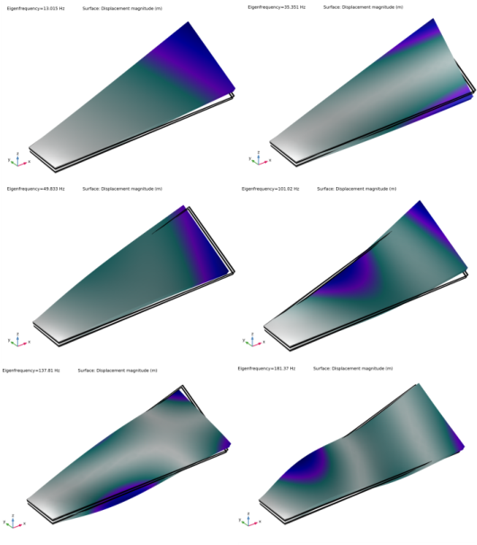
In the Settings window for 3D Plot Group, type Mode Shape (Multiple Model Method) in the Label text field.
|
|
3
|
|
4
|
|
1
|
|
2
|
|
3
|
|
1
|
In the Model Builder window, under Results>Mode Shape (Multiple Model Method) right-click Surface 1 and choose Duplicate.
|
|
2
|
|
3
|
|
4
|
|
5
|
|
1
|
|
2
|
|
3
|
|
4
|
|
5
|
|
1
|
In the Model Builder window, under Results>Mode Shape (Multiple Model Method) right-click Surface 2 and choose Duplicate.
|
|
2
|
|
3
|
|
1
|
|
2
|
|
3
|
|
4
|
|
5
|
|
1
|
|
2
|
|
1
|
|
2
|
|
3
|
|
4
|
|
5
|
|
1
|
|
2
|
|
3
|
|
4
|
In the Settings window for Study, type Study: Frequency (Multiple Model Method) in the Label text field.
|
|
5
|
|
6
|
|
1
|
|
2
|
|
3
|
|
1
|
|
2
|
|
3
|
|
4
|
|
1
|
|
2
|
|
3
|
|
4
|
|
5
|
|
1
|
In the Model Builder window, under Results>Stress (mises, peak) right-click Surface 1 and choose Duplicate.
|
|
2
|
|
3
|
|
4
|
|
1
|
|
2
|
|
3
|
|
4
|
|
5
|
|
1
|
|
2
|
|
3
|
|
1
|
|
2
|
|
3
|
|
4
|
|
5
|
|
1
|
|
2
|
|
3
|
|
1
|
|
2
|
|
1
|
|
2
|
|
3
|
Locate the Data section. From the Dataset list, choose Study: Frequency (Multiple Model Method)/Solution 2 (sol2).
|
|
4
|
|
1
|
|
2
|
|
3
|
|
4
|
|
1
|
|
2
|
|
1
|
|
2
|
|
3
|
In the Settings window for Layered Shell, type Layered Shell (Layerwise Theory) in the Label text field.
|
|
4
|
|
1
|
|
2
|
|
3
|
|
4
|
|
5
|
|
1
|
|
4
|
|
5
|
In the Settings window for Study, type Study: Eigenfrequency (Layerwise Theory) in the Label text field.
|
|
6
|
|
7
|
|
1
|
In the Model Builder window, under Results>Datasets right-click Layered Material 1 and choose Duplicate.
|
|
2
|
|
3
|
|
1
|
|
2
|
In the Settings window for 3D Plot Group, type Mode Shape (Layerwise Theory) in the Label text field.
|
|
3
|
|
4
|
|
1
|
In the Model Builder window, under Results>Mode Shape (Layerwise Theory), Ctrl-click to select Surface 2 and Surface 3.
|
|
2
|
Right-click and choose Delete.
|
|
1
|
|
2
|
|
3
|
|
1
|
|
2
|
|
3
|
|
4
|
|
5
|
|
1
|
|
2
|
|
3
|
|
4
|
|
5
|
|
1
|
|
2
|
|
3
|
|
4
|
|
5
|
|
1
|
|
2
|
|
3
|
|
5
|
|
6
|
|
7
|
|
8
|
|
1
|
In the Model Builder window, under Results>Datasets right-click Layered Material 2 and choose Duplicate.
|
|
2
|
|
3
|
|
1
|
|
2
|
|
3
|
Select the Enable check box.
|
|
4
|
|
5
|
|
1
|
|
2
|
|
3
|
|
1
|
|
2
|
|
3
|
|
1
|
|
2
|
|
3
|
|
4
|
|
5
|
|
6
|
|
1
|
|
2
|
|
3
|
|
4
|
|
5
|
|
1
|
|
2
|
|
1
|
|
2
|
|
3
|
Select the Enable check box.
|
|
4
|
|
5
|
|
1
|
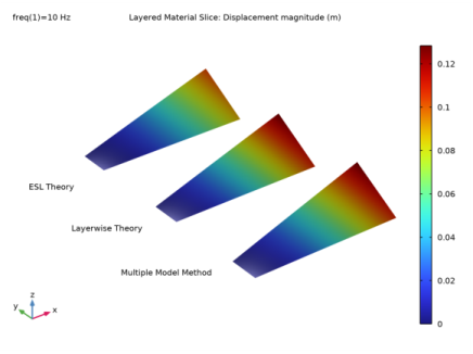
In the Model Builder window, under Results>Displacement Slice right-click Layered Material Slice 1 and choose Duplicate.
|
|
2
|
|
3
|
|
4
|
|
5
|
|
6
|
|
7
|
|
1
|
|
2
|
|
3
|
|
1
|
In the Model Builder window, expand the Component 1 (comp1)>Shell (ESL Theory) (shell3) node, then click Layered Linear Elastic Material 1.
|
|
2
|
|
3
|
|
1
|
|
2
|
|
4
|
|
5
|
|
1
|
|
2
|
|
3
|
|
1
|
|
2
|
|
3
|
|
4
|
|
5
|
|
1
|
|
4
|
|
5
|
|
6
|
|
7
|
|
1
|
In the Model Builder window, under Results>Datasets right-click Layered Material 1 and choose Duplicate.
|
|
2
|
|
3
|
|
1
|
|
2
|
|
3
|
|
1
|
|
2
|
|
3
|
|
1
|
|
2
|
|
3
|
|
4
|
|
5
|
|
1
|
|
2
|
|
3
|
|
4
|
|
5
|
|
1
|
|
2
|
|
3
|
|
4
|
|
5
|
|
1
|
|
2
|
|
3
|
|
5
|
|
6
|
|
7
|
|
8
|
|
1
|
In the Model Builder window, under Results>Datasets right-click Layered Material 4 and choose Duplicate.
|
|
2
|
|
3
|
|
1
|
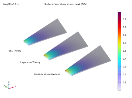
In the Model Builder window, under Results>Stress (mises, peak) right-click Surface 4 and choose Duplicate.
|
|
2
|
|
3
|
|
4
|
|
5
|
|
6
|
|
1
|
|
2
|
|
3
|
|
4
|
|
5
|
|
1
|
|
2
|
|
3
|
|
5
|
|
6
|
|
7
|
|
1
|
In the Model Builder window, under Results>Displacement Slice right-click Layered Material Slice 2 and choose Duplicate.
|
|
2
|
|
3
|
|
4
|
|
5
|
|
1
|
|
2
|
|
1
|
|
2
|
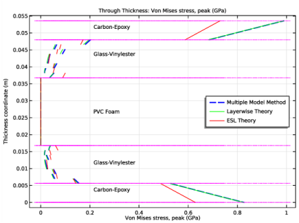
In the Settings window for 1D Plot Group, type Mises Peak Stress, Through Thickness in the Label text field.
|
|
3
|
Locate the Data section. From the Dataset list, choose Study: Frequency (Multiple Model Method)/Solution 2 (sol2).
|
|
4
|
|
1
|
|
3
|
|
4
|
|
5
|
|
6
|
Locate the y-Axis Data section. Find the Interface positions subsection. From the Show interface positions list, choose Interfaces between layered materials.
|
|
7
|
Click to expand the Coloring and Style section. Find the Line style subsection. From the Line list, choose Dashed.
|
|
8
|
|
9
|
|
10
|
|
11
|
|
1
|
|
2
|
|
3
|
|
4
|
|
5
|
|
1
|
|
2
|
|
3
|
|
1
|
In the Model Builder window, under Results>Mises Peak Stress, Through Thickness right-click Through Thickness 1 and choose Duplicate.
|
|
2
|
|
3
|
|
4
|
|
5
|
|
6
|
Locate the Coloring and Style section. Find the Line style subsection. From the Line list, choose Solid.
|
|
7
|
|
8
|
|
9
|
Locate the Legends section. In the table, enter the following settings:
|
|
1
|
|
2
|
|
3
|
|
4
|
|
5
|
|
6
|
Locate the Legends section. In the table, enter the following settings:
|
|
1
|
|
2
|
|
3
|
|
5
|
|
6
|
|
1
|
|
2
|
In the Settings window for Evaluation Group, type Maximum Mises Peak Stress Comparison in the Label text field.
|
|
3
|
|
4
|
|
1
|
|
2
|
|
1
|
|
2
|
|
3
|
|
4
|
Locate the Expressions section. In the table, enter the following settings:
|
|
1
|
|
2
|
|
3
|
|
4
|
Locate the Expressions section. In the table, enter the following settings:
|
|
5
|
|
1
|
|
2
|
In the Settings window for Evaluation Group, type Maximum Displacement Comparison in the Label text field.
|
|
3
|
|
4
|
|
1
|
|
2
|
|
1
|
|
2
|
|
3
|
|
4
|
Locate the Expressions section. In the table, enter the following settings:
|
|
1
|
|
2
|
|
3
|
|
4
|
Locate the Expressions section. In the table, enter the following settings:
|
|
5
|
|
1
|
|
2
|
In the Settings window for Evaluation Group, type Eigenfrequency Comparison in the Label text field.
|
|
3
|
|
1
|
|
2
|
|
1
|
|
2
|
|
3
|
|
1
|
|
2
|
|
3
|
|
4
|
|
1
|
In the Model Builder window, under Study: Eigenfrequency (Multiple Model Method) click Step 1: Eigenfrequency.
|
|
2
|
|
1
|
In the Model Builder window, under Study: Frequency (Multiple Model Method) click Step 1: Frequency Domain.
|
|
2
|
|
1
|
In the Model Builder window, under Study: Eigenfrequency (Layerwise Theory) click Step 1: Eigenfrequency.
|
|
2
|
|
1
|
In the Model Builder window, under Study: Frequency (Layerwise Theory) click Step 1: Frequency Domain.
|
|
2
|