PDF

Internal Short Circuit in a Lithium-Ion Battery
Introduction
During an internal short circuit of a battery the two electrode materials are internally interconnected electronically, giving rise to high local current densities. Internal short circuits may occur in a lithium-ion battery due to, for instance, lithium dendrite formation or a compressive shock. A prolonged internal short circuit results in self discharge in combination with a local temperature increase. The latter phenomena is of great importance since the electrolyte may start to decompose by exothermic reactions if the temperature reaches above a certain threshold level, causing thermal runaway with potential health and safety hazards.
This model example investigates the local temperature rise due to the occurrence of a penetrating metallic filament in the separator between the two porous electrode materials.
Model Definition
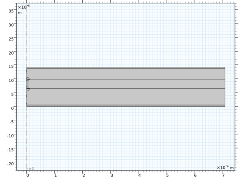
The model geometry is modeled as a layered disk made in 2D with axial symmetry. The penetrating filament is placed at r=0 and has the same height as the separator domain. The disk, with a cross-sectional area of about 1.3 mm2, is assumed to be a part of a much larger battery with a cross-sectional area in the order of 0.1 m2, or higher.
Figure 1: Model geometry. The rectangular layers represent (from the bottom): negative current collector, negative porous electrode, separator, positive porous electrode, positive current collector. The penetrating filament is placed at r=0 and has the same height as the separator domain.
The physics is set up by a Lithium-Ion Battery interface coupled to a Heat Transfer interface. The battery chemistry consists of a graphite negative electrode (50 μm thick) and a NMC positive electrode (40 μm thick) with LiPF6 electrolyte in 3:7 EC:EMC solvent (separator thickness 30 μm). 6 μm thick aluminum and copper current collectors are used on the positive and negative sides, respectively.
The total short-circuit current (< 10 mA) is assumed to be relatively low in relation to the total capacity (> 1 Ah) of the battery, so that over the investigated time period (0.1 s), the battery voltage outside the disk can be assumed to be constant. A constant cell potential is hence set on the outer radius of the disk. It is also assumed that the total heat capacity of the parts of the battery outside the modeled disk geometry, in combination with the high thermal conductivity of the metal foils, will result in the temperature of the outer rim of the disk to be constant during the simulated time period. Some of the temperature material parameters are taken from Ref. 1
The conductivity of the penetrating filament is set to a very low value at t=0 and ramped up to full conductivity at t=0.001 s using a smoothed step function.
Two different radii of the penetrating filament are investigated: 0.1 and 5 μm.
Results and Discussion
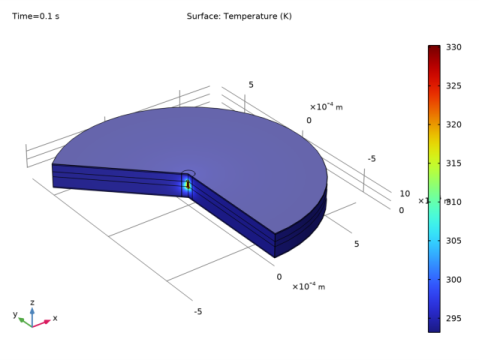
Figure 2 shows the temperature distribution at t=0.1 s for a penetrating filament radius of 5 μm. The maximum temperature is located close to the penetrating filament. The temperature change is confined to a small space close to the filament.
Figure 2: Temperature after 0.1 s for a radius of 5 μm.
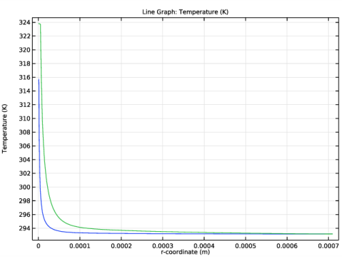
Figure 3 shows the temperature distribution along the separator-positive electrode boundary.
Figure 3: Temperature along the separator-positive electrode boundary.
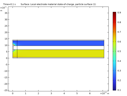
Figure 4 shows the local state-of-charge for a penetrating filament radius of 5 μm at t=0.1 s. Outside the close vicinity to the penetrating filament the battery is uniformly discharged. A conclusion from this (which would also be confirmed by analyzing the total current flowing through the nail in relation to the integrated reaction currents in the electrodes) is that it would suffice to use a secondary current distribution (that is, ignoring local concentration changes) to analyze the thermal behavior due to the short circuit. The dominating heat source is the ohmic heating in the filament and electrode phase close to the filament.
Figure 4: Local state of charge at t=0.1 s for a radius of 5 μm.
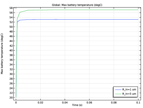
Figure 5 compares the maximum temperature in the cell for the two radii of the penetrating filament. The thicker radius causes a higher maximum temperature. This is related to the higher cross sectional area, resulting in a higher total short-circuit current.
Figure 5: Maximum cell temperature versus time.
Notes About the COMSOL Implementation
The parts of the porous electrodes closest to the shorting filaments are made inactive in the model. This is to facilitate numerical convergence.
Reference
1. Investigation of Short-Circuit Scenarios in a Lihtium-Ion Battery Cell, T. Zavalis, M. Behm, and G. Lindbergh, Journal of the Electrochemical Society, vol. 159, no. 6, pp A848–A859, 2012.
Application Library path: Battery_Design_Module/Batteries,_Lithium-Ion/internal_short_circuit
Modeling Instructions
From the File menu, choose New.
New
In the New window, click  Model Wizard.
Model Wizard
1
In the Model Wizard window, click  2D Axisymmetric.
2
In the Select Physics tree, select Electrochemistry>Batteries>Lithium-Ion Battery (liion).
3
Click Add.
4
In the Select Physics tree, select Heat Transfer>Heat Transfer in Solids (ht).
5
Click Add.
6
Click  Study.
7
In the Select Study tree, select Preset Studies for Selected Physics Interfaces>Lithium-Ion Battery>Time Dependent with Initialization.
8
Root
Load the model parameters from a text file.
Global Definitions
Parameters 1
1
In the Model Builder window, under Global Definitions click Parameters 1.
2
In the Settings window for Parameters, locate the Parameters section.
3
Click  Load from File.
4
Geometry 1
Rectangle 1 (r1)
1
In the Geometry toolbar, click  Rectangle.
2
In the Settings window for Rectangle, locate the Size and Shape section.
3
In the Width text field, type R_out.
4
In the Height text field, type L_tot.
5
Click to expand the Layers section. In the table, enter the following settings:
6
Click  Build Selected.
Polygon 1 (pol1)
1
In the Geometry toolbar, click  Polygon.
2
In the Settings window for Polygon, locate the Object Type section.
3
From the Type list, choose Open curve.
4
Locate the Coordinates section. In the table, enter the following settings:
Circle 1 (c1)
1
In the Geometry toolbar, click  Circle.
2
In the Settings window for Circle, locate the Size and Shape section.
3
In the Radius text field, type R_in*2.
4
In the Sector angle text field, type 90.
5
Locate the Position section. In the z text field, type L_negCC+L_neg+L_sep.
Circle 2 (c2)
1
Right-click Circle 1 (c1) and choose Duplicate.
2
In the Settings window for Circle, locate the Position section.
3
In the z text field, type L_negCC+L_neg.
4
Locate the Rotation Angle section. In the Rotation text field, type 270.
5
Click  Build Selected.
6
Click  Build Selected.
The geometry should now look like this:
Polygon 2 (pol2)
Finally also add a vertical line that will be used when meshing.
1
In the Geometry toolbar, click  Polygon.
2
In the Settings window for Polygon, locate the Object Type section.
3
From the Type list, choose Open curve.
4
Locate the Coordinates section. In the table, enter the following settings:
5
Click  Build Selected.
Definitions
Now create a number of selections on the geometry. These will be used later on when setting up the physics.
Negative CC
1
In the Definitions toolbar, click  Explicit.
2
In the Settings window for Explicit, type Negative CC in the Label text field.
3
Negative Electrode
1
In the Definitions toolbar, click  Explicit.
2
In the Settings window for Explicit, type Negative Electrode in the Label text field.
3
Separator
1
In the Definitions toolbar, click  Explicit.
2
In the Settings window for Explicit, type Separator in the Label text field.
3
Positive Electrode
1
In the Definitions toolbar, click  Explicit.
2
In the Settings window for Explicit, type Positive Electrode in the Label text field.
3
Positive CC
1
In the Definitions toolbar, click  Explicit.
2
In the Settings window for Explicit, type Positive CC in the Label text field.
3
Penetrating Filament
1
In the Definitions toolbar, click  Explicit.
2
In the Settings window for Explicit, type Penetrating Filament in the Label text field.
3
Metal Conductor Domains
1
In the Definitions toolbar, click  Union.
2
In the Settings window for Union, type Metal Conductor Domains in the Label text field.
3
Locate the Input Entities section. Under Selections to add, click  Add.
4
In the Add dialog box, in the Selections to add list, choose Negative CC, Positive CC, and Penetrating Filament.
5
Negative Terminal
1
In the Definitions toolbar, click  Explicit.
2
In the Settings window for Explicit, type Negative Terminal in the Label text field.
3
Locate the Input Entities section. From the Geometric entity level list, choose Boundary.
4
Positive Terminal
1
In the Definitions toolbar, click  Explicit.
2
In the Settings window for Explicit, type Positive Terminal in the Label text field.
3
Locate the Input Entities section. From the Geometric entity level list, choose Boundary.
4
Terminals
1
In the Definitions toolbar, click  Union.
2
In the Settings window for Union, type Terminals in the Label text field.
3
Locate the Geometric Entity Level section. From the Level list, choose Boundary.
4
Locate the Input Entities section. Under Selections to add, click  Add.
5
In the Add dialog box, in the Selections to add list, choose Negative Terminal and Positive Terminal.
6
Materials
Now add some materials from the material library.
Add Material
1
In the Home toolbar, click  Add Material to open the Add Material window.
2
Go to the Add Material window.
3
In the tree, select Built-in>Aluminum.
4
Click Add to Component in the window toolbar.
5
In the tree, select Built-in>Copper.
6
Click Add to Component in the window toolbar.
7
In the tree, select Battery>Electrodes>NMC 111, LiNi0.33Mn0.33Co0.33O2 (Positive, Li-ion Battery).
8
Click Add to Component in the window toolbar.
9
In the tree, select Battery>Electrodes>Graphite, LixC6 MCMB (Negative, Li-ion Battery).
10
Click Add to Component in the window toolbar.
11
In the tree, select Battery>Electrolytes>LiPF6 in 3:7 EC:EMC (Liquid, Li-ion Battery).
12
Click Add to Component in the window toolbar.
13
In the tree, select Battery>Electrodes>Lithium Metal, Li (Negative, Li-ion Battery).
14
Right-click and choose Add to Component 1 (comp1).
15
In the Home toolbar, click  Add Material to close the Add Material window.
Materials
Now assign the added materials to different parts of the geometry.
Aluminum (mat1)
1
In the Settings window for Material, locate the Geometric Entity Selection section.
2
From the Selection list, choose Positive CC.
Copper (mat2)
1
In the Model Builder window, click Copper (mat2).
2
In the Settings window for Material, locate the Geometric Entity Selection section.
3
From the Selection list, choose Negative CC.
NMC 111, LiNi0.33Mn0.33Co0.33O2 (Positive, Li-ion Battery) (mat3)
1
In the Model Builder window, click NMC 111, LiNi0.33Mn0.33Co0.33O2 (Positive, Li-ion Battery) (mat3).
2
In the Settings window for Material, locate the Geometric Entity Selection section.
3
From the Selection list, choose Positive Electrode.
Graphite, LixC6 MCMB (Negative, Li-ion Battery) (mat4)
1
In the Model Builder window, click Graphite, LixC6 MCMB (Negative, Li-ion Battery) (mat4).
2
In the Settings window for Material, locate the Geometric Entity Selection section.
3
From the Selection list, choose Negative Electrode.
LiPF6 in 3:7 EC:EMC (Liquid, Li-ion Battery) (mat5)
1
In the Model Builder window, click LiPF6 in 3:7 EC:EMC (Liquid, Li-ion Battery) (mat5).
2
In the Settings window for Material, locate the Geometric Entity Selection section.
3
From the Selection list, choose Separator.
Lithium Metal, Li (Negative, Li-ion Battery) (mat6)
1
In the Model Builder window, click Lithium Metal, Li (Negative, Li-ion Battery) (mat6).
2
In the Settings window for Material, locate the Geometric Entity Selection section.
3
From the Selection list, choose Penetrating Filament.
Some of the added materials are marked with a red cross, indicating missing material properties. You will go back at a later stage to fill in the missing values.
Lithium-Ion Battery (liion)
Now start setting up the physics, beginning with the lithium-ion battery.
Porous Electrode 1 (Negative)
1
In the Model Builder window, under Component 1 (comp1) right-click Lithium-Ion Battery (liion) and choose Porous Electrode.
2
In the Settings window for Porous Electrode, type Porous Electrode 1 (Negative) in the Label text field.
3
Locate the Domain Selection section. From the Selection list, choose Negative Electrode.
4
Locate the Electrolyte Properties section. From the Electrolyte material list, choose LiPF6 in 3:7 EC:EMC (Liquid, Li-ion Battery) (mat5).
5
Locate the Electrode Properties section. From the Electrode material list, choose Graphite, LixC6 MCMB (Negative, Li-ion Battery) (mat4).
6
Locate the Porous Matrix Properties section. In the εs text field, type epss_neg.
7
In the εl text field, type epsl_neg.
Particle Intercalation 1
1
In the Model Builder window, expand the Porous Electrode 1 (Negative) node, then click Particle Intercalation 1.
2
In the Settings window for Particle Intercalation, locate the Material section.
3
From the Particle material list, choose Graphite, LixC6 MCMB (Negative, Li-ion Battery) (mat4).
4
Locate the Particle Transport Properties section. In the rp text field, type rp_neg.
5
Click to expand the Heat of Mixing section. Select the Include heat of mixing check box.
Porous Electrode Reaction 1
1
In the Model Builder window, click Porous Electrode Reaction 1.
2
In the Settings window for Porous Electrode Reaction, locate the Material section.
3
From the Material list, choose Graphite, LixC6 MCMB (Negative, Li-ion Battery) (mat4).
4
Locate the Electrode Kinetics section. In the i0,ref(T) text field, type i0ref_neg.
Porous Electrode 1 (Negative)
Duplicate the node to create the positive porous electrode, and change only the parameters that differ from the negative.
Porous Electrode 2 (Positive)
1
In the Model Builder window, right-click Porous Electrode 1 (Negative) and choose Duplicate.
2
In the Settings window for Porous Electrode, type Porous Electrode 2 (Positive) in the Label text field.
3
Locate the Domain Selection section. From the Selection list, choose Positive Electrode.
4
Locate the Electrode Properties section. From the Electrode material list, choose NMC 111, LiNi0.33Mn0.33Co0.33O2 (Positive, Li-ion Battery) (mat3).
5
Locate the Porous Matrix Properties section. In the εs text field, type epss_pos.
6
In the εl text field, type epsl_pos.
Particle Intercalation 1
1
In the Model Builder window, expand the Porous Electrode 2 (Positive) node, then click Particle Intercalation 1.
2
In the Settings window for Particle Intercalation, locate the Material section.
3
From the Particle material list, choose NMC 111, LiNi0.33Mn0.33Co0.33O2 (Positive, Li-ion Battery) (mat3).
4
Locate the Particle Transport Properties section. In the rp text field, type rp_pos.
Porous Electrode Reaction 1
1
In the Model Builder window, click Porous Electrode Reaction 1.
2
In the Settings window for Porous Electrode Reaction, locate the Material section.
3
From the Material list, choose NMC 111, LiNi0.33Mn0.33Co0.33O2 (Positive, Li-ion Battery) (mat3).
4
Locate the Electrode Kinetics section. In the i0,ref(T) text field, type i0ref_pos.
Porous Electrode 1 (Negative, Electrochemically Inactive)
1
In the Model Builder window, right-click Porous Electrode 1 (Negative) and choose Duplicate.
2
In the Settings window for Porous Electrode, type Porous Electrode 1 (Negative, Electrochemically Inactive) in the Label text field.
3
4
Locate the Particle Properties section. From the list, choose Nonintercalating particles.
Porous Electrode Reaction 1
1
In the Model Builder window, expand the Porous Electrode 1 (Negative, Electrochemically Inactive) node, then click Porous Electrode Reaction 1.
2
In the Settings window for Porous Electrode Reaction, locate the Equilibrium Potential section.
3
From the Eeq list, choose User defined. In the associated text field, type 0.1[V].
4
Locate the Electrode Kinetics section. From the iloc,expr list, choose User defined. Click to expand the Heat of Reaction section. From the dEeq/dT list, choose User defined.
Porous Electrode 2 (Positive, Electrochemically Inactive)
1
In the Model Builder window, right-click Porous Electrode 2 (Positive) and choose Duplicate.
2
In the Settings window for Porous Electrode, type Porous Electrode 2 (Positive, Electrochemically Inactive) in the Label text field.
3
4
Locate the Particle Properties section. From the list, choose Nonintercalating particles.
Porous Electrode Reaction 1
1
In the Model Builder window, expand the Porous Electrode 2 (Positive, Electrochemically Inactive) node, then click Porous Electrode Reaction 1.
2
In the Settings window for Porous Electrode Reaction, locate the Equilibrium Potential section.
3
From the Eeq list, choose User defined. In the associated text field, type 0.1[V]+E_cell.
4
Locate the Electrode Kinetics section. From the iloc,expr list, choose User defined. Locate the Heat of Reaction section. From the dEeq/dT list, choose User defined.
Electrode 1 (CCs and Filament)
The electronically conducting domains are specified using one common Electrode node. Different material parameters will be specified for these domains in the Materials node.
1
In the Physics toolbar, click  Domains and choose Electrode.
2
In the Settings window for Electrode, locate the Domain Selection section.
3
From the Selection list, choose Metal Conductor Domains.
4
In the Label text field, type Electrode 1 (CCs and Filament).
Separator 1
1
In the Physics toolbar, click  Domains and choose Separator.
2
In the Settings window for Separator, locate the Domain Selection section.
3
From the Selection list, choose Separator.
4
Locate the Porous Matrix Properties section. In the εl text field, type epsl_sep.
Electric Ground 1
1
In the Physics toolbar, click  Boundaries and choose Electric Ground.
2
In the Settings window for Electric Ground, locate the Boundary Selection section.
3
From the Selection list, choose Negative Terminal.
Electric Potential 1
1
In the Physics toolbar, click  Boundaries and choose Electric Potential.
2
In the Settings window for Electric Potential, locate the Boundary Selection section.
3
From the Selection list, choose Positive Terminal.
4
Locate the Electric Potential section. In the φs,bnd text field, type E_cell.
Use an Initial Cell Charge Distribution node to specify the initial cell voltage and the capacity of the battery.
Initial Cell Charge Distribution 1
1
In the Physics toolbar, click  Global and choose Initial Cell Charge Distribution.
2
In the Settings window for Initial Cell Charge Distribution, locate the Battery Cell Parameters section.
3
In the Ecell,0 text field, type E_cell.
4
In the Qcell,0 text field, type Q_batt.
Negative Electrode Selection 1
1
In the Model Builder window, expand the Initial Cell Charge Distribution 1 node, then click Negative Electrode Selection 1.
2
Positive Electrode Selection 1
1
In the Model Builder window, click Positive Electrode Selection 1.
2
Heat Transfer in Solids (ht)
Now set up the Heat Transfer part of the problem. All domain specific material parameters will be set up by the Materials node, so the default Heat Transfer in Solids node can be used in all domains.
In the Model Builder window, under Component 1 (comp1) click Heat Transfer in Solids (ht).
Temperature 1
1
In the Physics toolbar, click  Boundaries and choose Temperature.
2
In the Settings window for Temperature, locate the Boundary Selection section.
3
From the Selection list, choose Terminals.
4
Locate the Temperature section. In the T0 text field, type T0.
Initial Values 1
1
In the Model Builder window, click Initial Values 1.
2
In the Settings window for Initial Values, locate the Initial Values section.
3
In the T text field, type T0.
Multiphysics
Electrochemical Heating 1 (ech1)
In the Physics toolbar, click  Multiphysics Couplings and choose Domain>Electrochemical Heating.
Materials
Now go back to the Materials node and fill in the missing parameters to remove the red crosses.
NMC 111, LiNi0.33Mn0.33Co0.33O2 (Positive, Li-ion Battery) (mat3)
1
In the Model Builder window, under Component 1 (comp1)>Materials click NMC 111, LiNi0.33Mn0.33Co0.33O2 (Positive, Li-ion Battery) (mat3).
2
In the Settings window for Material, locate the Material Contents section.
3
LiPF6 in 3:7 EC:EMC (Liquid, Li-ion Battery) (mat5)
1
In the Model Builder window, click LiPF6 in 3:7 EC:EMC (Liquid, Li-ion Battery) (mat5).
2
In the Settings window for Material, locate the Material Contents section.
3
Definitions (comp1)
For the electric conductivity of the penetrating filament we will use a step function to ramp up the conductivity at t = 0.
Step 1 (step1)
1
In the Home toolbar, click  Functions and choose Global>Step.
2
In the Settings window for Step, locate the Parameters section.
3
In the Location text field, type 0.5.
4
Click to expand the Smoothing section. In the Size of transition zone text field, type 1.
Materials
Lithium Metal, Li (Negative, Li-ion Battery) (mat6)
1
In the Model Builder window, under Component 1 (comp1)>Materials click Lithium Metal, Li (Negative, Li-ion Battery) (mat6).
2
In the Settings window for Material, locate the Material Contents section.
3
The red cross on the Materials node should now be gone.
Mesh 1
Create the mesh using a triangular mesh close to the filament, and then a mapped mesh with a growing element size in the x direction for the remaining domains.
Free Triangular 1
1
In the Mesh toolbar, click  Free Triangular.
2
In the Settings window for Free Triangular, locate the Domain Selection section.
3
From the Geometric entity level list, choose Domain.
4
Distribution 1
1
Right-click Free Triangular 1 and choose Distribution.
2
In the Settings window for Distribution, locate the Boundary Selection section.
3
Click  Paste Selection.
4
In the Paste Selection dialog box, type 35 36 in the Selection text field.
5
6
In the Settings window for Distribution, locate the Distribution section.
7
In the Number of elements text field, type 10.
Mapped 1
1
In the Mesh toolbar, click  Mapped.
2
In the Settings window for Mapped, click to expand the Control Entities section.
3
Clear the Smooth across removed control entities check box.
Distribution 1
1
Right-click Mapped 1 and choose Distribution.
2
In the Settings window for Distribution, locate the Boundary Selection section.
3
Click  Paste Selection.
4
In the Paste Selection dialog box, type 20, 22, 24, 26, 28-29 in the Selection text field.
5
6
In the Settings window for Distribution, locate the Distribution section.
7
From the Distribution type list, choose Predefined.
8
In the Number of elements text field, type 20.
9
In the Element ratio text field, type 10.
10
Select the Reverse direction check box.
11
Click  Build All.
The finalized mesh should look like this:
Definitions (comp1)
Add a probe to monitor the maximum temperature of the cell while solving.
Max temperature probe
1
In the Definitions toolbar, click  Probes and choose Domain Probe.
2
In the Settings window for Domain Probe, type Max temperature probe in the Label text field.
3
Locate the Probe Type section. From the Type list, choose Maximum.
4
Locate the Expression section. In the Expression text field, type T.
Maximum 1 (maxop1)
Also add a maximum operator that will be used while postprocessing once the model is solved.
1
In the Definitions toolbar, click  Nonlocal Couplings and choose Maximum.
2
In the Settings window for Maximum, locate the Source Selection section.
3
From the Selection list, choose All domains.
Study 1
The physics and mesh settings are now complete. The model is to be solved in two steps. The first step is used to initialize the battery cell. Turn off solving for Heat Transfer in the first solver step.
Step 1: Current Distribution Initialization
1
In the Model Builder window, under Study 1 click Step 1: Current Distribution Initialization.
2
In the Settings window for Current Distribution Initialization, locate the Physics and Variables Selection section.
3
In the table, clear the Solve for check box for Heat Transfer in Solids (ht).
Step 2: Time Dependent
1
In the Model Builder window, click Step 2: Time Dependent.
2
In the Settings window for Time Dependent, locate the Study Settings section.
3
In the Output times text field, type 0 10^range(-3,0.5,-1).
Parametric Sweep
Use a Parametric Sweep to solve for two different radii of the penetrating filament.
1
In the Study toolbar, click  Parametric Sweep.
2
In the Settings window for Parametric Sweep, locate the Study Settings section.
3
4
5
In the Model Builder window, click Study 1.
6
In the Settings window for Study, locate the Study Settings section.
7
Clear the Generate default plots check box.
8
In the Study toolbar, click  Compute.
Results
Revolution 2D 1
Plot a revolution plot of the temperature (Figure 2) as follows:
1
In the Results toolbar, click  More Datasets and choose Revolution 2D.
2
In the Settings window for Revolution 2D, click to expand the Revolution Layers section.
3
In the Start angle text field, type -90.
4
In the Revolution angle text field, type 225.
Temperature (revolution plot)
1
In the Results toolbar, click  3D Plot Group.
2
In the Settings window for 3D Plot Group, type Temperature (revolution plot) in the Label text field.
Surface 1
1
Right-click Temperature (revolution plot) and choose Surface.
2
In the Settings window for Surface, locate the Expression section.
3
In the Expression text field, type T.
4
In the Temperature (revolution plot) toolbar, click  Plot.
Temperature along separator
Plot the temperature along the separator-positive electrode boundary (Figure 3) as follows:
1
In the Home toolbar, click  Add Plot Group and choose 1D Plot Group.
2
In the Settings window for 1D Plot Group, type Temperature along separator in the Label text field.
3
Locate the Data section. From the Dataset list, choose Study 1/Parametric Solutions 1 (sol3).
4
From the Time selection list, choose Last.
Line Graph 1
1
Right-click Temperature along separator and choose Line Graph.
2
3
In the Settings window for Line Graph, locate the y-Axis Data section.
4
In the Expression text field, type T.
5
Locate the x-Axis Data section. From the Parameter list, choose Expression.
6
In the Expression text field, type r.
7
In the Temperature along separator toolbar, click  Plot.
Local soc
Plot the local state-of-charge (Figure 4) as follows:
1
In the Home toolbar, click  Add Plot Group and choose 2D Plot Group.
2
In the Settings window for 2D Plot Group, type Local soc in the Label text field.
Surface 1
1
Right-click Local soc and choose Surface.
2
In the Settings window for Surface, click Replace Expression in the upper-right corner of the Expression section. From the menu, choose Component 1 (comp1)>Lithium-Ion Battery>Particle intercalation>liion.socloc_surface - Local electrode material state-of-charge, particle surface.
3
In the Local soc toolbar, click  Plot.
Max temperature vs. time
Plot the maximum temperature versus time (Figure 5) as follows:
1
In the Home toolbar, click  Add Plot Group and choose 1D Plot Group.
2
In the Settings window for 1D Plot Group, type Max temperature vs. time in the Label text field.
3
Locate the Data section. From the Dataset list, choose Study 1/Parametric Solutions 1 (sol3).
4
Locate the Legend section. From the Position list, choose Lower right.
Global 1
1
Right-click Max temperature vs. time and choose Global.
2
In the Settings window for Global, locate the y-Axis Data section.
3
4
Click to expand the Legends section. Find the Include subsection. Clear the Description check box.
5
In the Max temperature vs. time toolbar, click  Plot.