PDF

Piezoelectric MEMS Speaker
Introduction
This model analyzes a piezoelectric microelectromechanical system (MEMS) speaker presented in Ref. 1, 2, and 3. The speaker, composed of four triangular membranes, uses a layer of lead zirconate titanate (PZT) material with two electrodes on opposing faces as actuator. The triangular membranes are separated by narrow gaps of air that allow for larger deflections of the membrane. The thermoviscous losses in the gaps limit the airflow, thus allowing the four actuators to behave acoustically as a single membrane.
Model Definition
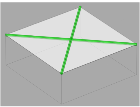
The PZT material, which seats on top of a silicon layer, is excited with a voltage that makes the membrane move and create sound. Figure 1 shows a schematic view of the speaker. The four triangular membranes are separated by narrow gaps of air. The acoustic behavior in the gaps (shown in green) is modeled with the full thermoviscous acoustic formulation using the Thermoviscous Acoustics, Frequency Domain physics interface.
Figure 1: Schematic representation of the piezoelectric MEMS speaker, with the areas where thermoviscous losses are relevant highlighted in green.
The four triangular membranes form a square with approximately 4 mm sides. The membrane is backed by a back volume of roughly 24 mm3. The volume acts as a spring (compliance) changing the acoustic properties of the speaker.
The tutorial takes advantage of the existing symmetries to model only a quarter of the speaker and represent the rest by using symmetry features. The speaker is located in an infinite baffle and uses a voltage difference acting between the faces of the PZT material to create vibrations that will propagate as acoustic perturbations. The acting voltage contains a constant component, usually called the bias voltage (DC) and an alternating voltage (AC or perturbation contribution), following
(1)
where V0 is the terminal voltage, VDC is the bias voltage, VAC is the alternating voltage, f is the driving frequency, and t is the time. Due to the piezoelectric effect, the PZT material excited with this voltage will induce deformations in the membranes, which are captured through the Solid Mechanics physics.
The air gap between the membranes is 9 μm wide, and this gap is in the order of magnitude of the viscous boundary layer in air (at the frequencies studied here). The boundary layer thickness is given by
(2)
where δv is the viscous boundary layer thickness (in the second equation the material properties of air have been entered). At the resonance frequency of 9 kHz, δv takes the value of 23.2 μm, on the same order of magnitude as the gap. This indicates that the thermoviscous losses are likely to modify the response of the speaker at the driving frequency. To capture the losses, the Thermoviscous Acoustics, Frequency Domain is used to model the acoustics in the air gaps and a small surrounding volume.
The rest of the acoustic domains are captured using the Pressure Acoustics, Frequency Domain physics interface. Here the thermoviscous boundary layers are captured through the Thermoviscous Boundary Layer Impedance boundary condition. The open domain conditions surrounding the speaker is modeled with a Perfectly Matched Layer. The Exterior Field Calculation feature is used to obtain the acoustic field at any point in the exterior domain.
Results and Discussion
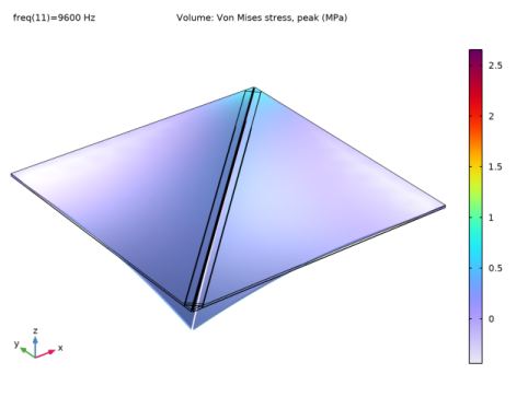
The harmonic component of the stress in the membrane is shown in Figure 2. Note how the excitation produces displacement perpendicular to the plane of the membrane through bending.
Figure 2: Harmonic part of the von Mises stress at the membranes.
Figure 3 shows the distribution of the electric potential in the membranes. The electric potential variation takes place almost exclusively in the vertical direction. As seen in Figure 4, the small dimensions of the speaker means that the computational domain does not even capture a full wavelength at the highest frequency analyzed, 20 kHz.
Figure 3: Harmonic variation of the electric potential.
Figure 4: Total acoustic pressure at 20 kHz.
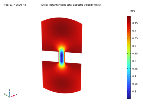
Figure 5 shows the instantaneous acoustic velocity around the air gaps. The high velocity gradients present in the air gaps create viscous shear losses that damp the natural frequency of the membranes. Note that the section shown is close to the center of the membrane, so the complete section has a velocity larger than 0.
Figure 5: Instantaneous local velocity at 9 kHz.
The logarithmic thermoviscous losses, shown in Figure 6 demonstrate how most of the thermoviscous losses are concentrated in the air gap, suggesting that a Narrow Region Acoustics feature (using the slit option) in Pressure Acoustics could potentially be enough to capture the losses caused by the air gap. This requires that the gap is not significantly modified during operation. This is discussed further in the Notes About the COMSOL Implementation section below.
Figure 6: Logarithmic volumetric thermoviscous losses around the air gap.
Figure 7 shows the magnitude and phase of the electric impedance of the speaker. The electric impedance shows excellent agreement with the experimental results in Ref. 1, 2, and 3.
Figure 7: Electric impedance of the speaker, magnitude and phase.
Notes About the COMSOL Implementation
The model uses the Small-Signal Analysis to analyze the static effect of the bias voltage and the harmonic perturbation caused by the alternating voltage. To include the effects of the DC part (prestress and deformation) it is important that the Include geometric nonlinearity is selected in the Frequency Domain Perturbation study step.
The model is solved in the frequency domain which assumes small deformations (small signal assumption). This means that, for example, topological changes of the air gap are not captured (the gap effectively remains the same) in the simulation. This is an assumption made when working in the frequency domain. At the resonance the maximum deflection is a bout 4 µm which is on top of the static DC deformation of about 3 µm (see plot in the model). The gap width is 9 µm and the gap height is 17 µm, so at resonance the small signal assumption is probably not fully valid. The topological changes can be included in the model by using the Moving Mesh functionality. Including the dynamic topology changes on top of the DC deformation requires solving a transient model.
The model uses the Added Mass feature under Solid Mechanics to represent the masses of the electrodes, which have a significant effect on the resonance frequencies.
The model uses a Boundary Load to manually couple the Solid Mechanics and the Pressure Acoustics, Frequency Domain physics. This manual coupling is done to be able to capture the effects of the thermoviscous boundary layer impedance in those areas where there is a coupling between the two physics. The Thermoviscous Boundary Layer Impedance is used to capture the boundary layer losses in those boundaries that are in contact with the Pressure Acoustics, Frequency Domain physics.
The Thermoviscous Boundary Layer Impedance condition is an inexpensive way to include the effects of the thermoviscous boundary layers. The condition is valid for models where there is no overlap between boundary layers, as it is the case for the current model. A small overlap will be present at the corners of the back volume but this effect is minimal.
References
1. F. Stoppel, A.Männchen, F. Niekiel, D. Beer, T. Giese, and B. Wagner, “New integrated full-range MEMS speaker for in-ear applications,” IEEE Micro Electro Mechanical Systems (MEMS), 2018.
2. A.Männchen, F. Stoppel, D. Beer, F. Niekiel, and B. Wagner, “In-ear headphone system with piezoelectric MEMS driver,” Audio Engineering Society, 2018.
3. A.Männchen, F. Stoppel, T. Brocks, F. Niekiel, D. Beer, and B. Wagner, “Design and electroacoustic analysis of a piezoelectric MEMS in-ear headphone,” Audio Engineering Society, 2018.
Application Library path: Acoustics_Module/Electroacoustic_Transducers/piezo_mems_speaker
Modeling Instructions
From the File menu, choose New.
New
In the New window, click  Model Wizard.
Model Wizard
1
In the Model Wizard window, click  3D.
2
In the Select Physics tree, select Structural Mechanics>Electromagnetics-Structure Interaction>Piezoelectricity>Piezoelectricity, Solid.
3
Click Add.
4
In the Select Physics tree, select Acoustics>Pressure Acoustics>Pressure Acoustics, Frequency Domain (acpr).
5
Click Add.
6
In the Select Physics tree, select Acoustics>Thermoviscous Acoustics>Thermoviscous Acoustics, Frequency Domain (ta).
7
Click Add.
8
Click  Study.
9
In the Select Study tree, select Preset Studies for Selected Physics Interfaces>Electrostatics>Small-Signal Analysis, Frequency Domain.
10
Geometry 1
Adjust the units of the model to µm.
1
In the Model Builder window, under Component 1 (comp1) click Geometry 1.
2
In the Settings window for Geometry, locate the Units section.
3
From the Length unit list, choose µm.
Import the parameters from an external file. This file contains parameters like dimensions, maximum frequency and voltage that define the current model.
Global Definitions
Parameters 1
1
In the Model Builder window, under Global Definitions click Parameters 1.
2
In the Settings window for Parameters, locate the Parameters section.
3
Click  Load from File.
4
Import the geometry from an external file.
Geometry 1
1
In the Geometry toolbar, click Insert Sequence and choose Insert Sequence.
2
3
In the Geometry toolbar, click  Build All.
4
Click the  Show Grid button in the Graphics toolbar.
5
Click the  Transparency button in the Graphics toolbar.
The picture should like this.
6
Click the  Transparency button in the Graphics toolbar.
Definitions
Linear Extrusion 1 (linext1)
1
In the Definitions toolbar, click  Nonlocal Couplings and choose Linear Extrusion.
We will use the Linear Extrusion feature to generate result plots later on.
2
In the Settings window for Linear Extrusion, locate the Source Selection section.
3
From the Geometric entity level list, choose Edge.
4
5
Locate the Source Vertices section. Click to select the  Activate Selection toggle button.
6
7
Click to select the  Activate Selection toggle button.
8
9
Locate the Destination Vertices section. Click to select the  Activate Selection toggle button.
10
11
Click to select the  Activate Selection toggle button.
12
Perfectly Matched Layer 1 (pml1)
1
In the Definitions toolbar, click  Perfectly Matched Layer.
2
In the Settings window for Perfectly Matched Layer, locate the Domain Selection section.
3
From the Selection list, choose PML Domains.
4
Locate the Geometry section. From the Type list, choose Cylindrical.
5
Locate the Scaling section. From the Physics list, choose Pressure Acoustics, Frequency Domain (acpr).
Geometry 1
In the Model Builder window, collapse the Component 1 (comp1)>Geometry 1 node.
Materials
Apply materials to the model. Use the Air and Silicon materials from the Built-in category and the PZT material from the Piezoelectric category.
Add Material
1
In the Home toolbar, click  Add Material to open the Add Material window.
2
Go to the Add Material window.
3
4
Click Add to Component in the window toolbar.
5
In the tree, select Piezoelectric>Lead Zirconate Titanate (PZT-4).
6
Click Add to Component in the window toolbar.
7
In the tree, select Built-in>Silicon.
8
Click Add to Component in the window toolbar.
9
In the Home toolbar, click  Add Material to close the Add Material window.
Materials
Silicon (mat3)
1
In the Settings window for Material, locate the Geometric Entity Selection section.
2
From the Selection list, choose Silicon Domains.
Lead Zirconate Titanate (PZT-4) (mat2)
1
In the Model Builder window, click Lead Zirconate Titanate (PZT-4) (mat2).
2
In the Settings window for Material, locate the Geometric Entity Selection section.
3
From the Selection list, choose PZT Domains.
Air (mat1)
1
In the Model Builder window, click Air (mat1).
2
In the Settings window for Material, locate the Geometric Entity Selection section.
3
From the Selection list, choose Air Domains.
Solid Mechanics (solid)
1
In the Model Builder window, under Component 1 (comp1) click Solid Mechanics (solid).
2
In the Settings window for Solid Mechanics, locate the Domain Selection section.
3
From the Selection list, choose Structural Domains.
Add the Piezoelectric Material feature to the PZT domain so the piezoelectric forces are computed correctly.
Piezoelectric Material 1
1
In the Model Builder window, under Component 1 (comp1)>Solid Mechanics (solid) click Piezoelectric Material 1.
2
In the Settings window for Piezoelectric Material, locate the Domain Selection section.
3
From the Selection list, choose PZT Domains.
Fixed Constraint 1
1
In the Physics toolbar, click  Boundaries and choose Fixed Constraint.
2
In the Settings window for Fixed Constraint, locate the Boundary Selection section.
3
Click  Clear Selection.
4
Symmetry 1
1
In the Physics toolbar, click  Boundaries and choose Symmetry.
2
In the Settings window for Symmetry, locate the Boundary Selection section.
3
From the Selection list, choose Symmetric Boundaries.
Add the mass representing the electrodes as this mass influences the eigenfrequencies of the system.
Added Mass - Pt Electrode
1
In the Physics toolbar, click  Boundaries and choose Added Mass.
2
In the Settings window for Added Mass, type Added Mass - Pt Electrode in the Label text field.
3
Locate the Boundary Selection section. From the Selection list, choose Ground.
4
Locate the Added Mass section. In the ρA text field, type rho_pt*th_pt.
Added Mass - Au Electrode
1
In the Physics toolbar, click  Boundaries and choose Added Mass.
2
In the Settings window for Added Mass, type Added Mass - Au Electrode in the Label text field.
3
Locate the Boundary Selection section. From the Selection list, choose Terminal.
4
Locate the Added Mass section. In the ρA text field, type rho_au*th_au.
Boundary Load 1
1
In the Physics toolbar, click  Boundaries and choose Boundary Load.
2
3
In the Settings window for Boundary Load, locate the Force section.
4
From the Load type list, choose Pressure.
This adds the acoustic load as a boundary load.
5
In the p text field, type acpr.p_t.
To reduce the computation time of the model, we will only model the electrostatics effects in the membrane and the air around the gap.
Electrostatics (es)
1
In the Model Builder window, under Component 1 (comp1) click Electrostatics (es).
2
In the Settings window for Electrostatics, locate the Domain Selection section.
3
From the Selection list, choose Electrostatics Domains.
Charge Conservation, Piezoelectric 1
1
In the Model Builder window, under Component 1 (comp1)>Electrostatics (es) click Charge Conservation, Piezoelectric 1.
2
In the Settings window for Charge Conservation, Piezoelectric, locate the Domain Selection section.
3
From the Selection list, choose PZT Domains.
Ground 1
1
In the Physics toolbar, click  Boundaries and choose Ground.
2
In the Settings window for Ground, locate the Boundary Selection section.
3
From the Selection list, choose Ground.
Terminal 1
1
In the Physics toolbar, click  Boundaries and choose Terminal.
2
In the Settings window for Terminal, locate the Boundary Selection section.
3
From the Selection list, choose Terminal.
4
Locate the Terminal section. From the Terminal type list, choose Voltage.
5
In the V0 text field, type V_DC+linper(V_AC).
The speaker has a bias voltage that will be considered in the Stationary step of the analysis. Use the linper operator to discern the variable part of the voltage that will be used in the Frequency Domain Perturbation step.
Pressure Acoustics, Frequency Domain (acpr)
1
In the Model Builder window, under Component 1 (comp1) click Pressure Acoustics, Frequency Domain (acpr).
2
In the Settings window for Pressure Acoustics, Frequency Domain, locate the Domain Selection section.
3
From the Selection list, choose Pressure Acoustics Domains.
4
Click to expand the Discretization section.
Symmetry 1
1
In the Physics toolbar, click  Boundaries and choose Symmetry.
2
In the Settings window for Symmetry, locate the Boundary Selection section.
3
From the Selection list, choose Symmetric Boundaries.
Exterior Field Calculation 1
1
In the Physics toolbar, click  Boundaries and choose Exterior Field Calculation.
2
In the Settings window for Exterior Field Calculation, locate the Boundary Selection section.
3
From the Selection list, choose Exterior Field Boundaries.
4
Locate the Exterior Field Calculation section. From the Condition in the x = x0 plane list, choose Symmetric/Infinite sound hard boundary.
5
From the Condition in the y = y0 plane list, choose Symmetric/Infinite sound hard boundary.
6
From the Condition in the z = z0 plane list, choose Symmetric/Infinite sound hard boundary.
Thermoviscous Boundary Layer Impedance 1
1
In the Physics toolbar, click  Boundaries and choose Thermoviscous Boundary Layer Impedance.
2
In the Settings window for Thermoviscous Boundary Layer Impedance, locate the Fluid Properties section.
3
From the Fluid material list, choose Air (mat1).
4
Thermoviscous Boundary Layer Impedance 2
1
In the Physics toolbar, click  Boundaries and choose Thermoviscous Boundary Layer Impedance.
2
3
In the Settings window for Thermoviscous Boundary Layer Impedance, locate the Fluid Properties section.
4
From the Fluid material list, choose Air (mat1).
Now add the solid velocity to make the manual coupling.
5
Locate the Mechanical Condition section. From the Mechanical condition list, choose Velocity.
6
Specify the v0 vector as
Thermoviscous Acoustics, Frequency Domain (ta)
1
In the Model Builder window, under Component 1 (comp1) click Thermoviscous Acoustics, Frequency Domain (ta).
2
In the Settings window for Thermoviscous Acoustics, Frequency Domain, locate the Domain Selection section.
3
From the Selection list, choose Thermoviscous Domains.
Symmetry 1
1
In the Physics toolbar, click  Boundaries and choose Symmetry.
2
In the Settings window for Symmetry, locate the Boundary Selection section.
3
From the Selection list, choose Symmetric Boundaries.
Add the missing multiphysics couplings that will handle the interaction between the different physics. Thermoviscous acoustics to the structure and the coupling between thermoviscous acoustics and pressure acoustics.
Multiphysics
Thermoviscous Acoustic-Structure Boundary 1 (tsb1)
1
In the Physics toolbar, click  Multiphysics Couplings and choose Boundary>Thermoviscous Acoustic-Structure Boundary.
2
In the Settings window for Thermoviscous Acoustic-Structure Boundary, locate the Boundary Selection section.
3
From the Selection list, choose All boundaries.
Acoustic-Thermoviscous Acoustic Boundary 1 (atb1)
1
In the Physics toolbar, click  Multiphysics Couplings and choose Boundary>Acoustic-Thermoviscous Acoustic Boundary.
2
In the Settings window for Acoustic-Thermoviscous Acoustic Boundary, locate the Boundary Selection section.
3
From the Selection list, choose All boundaries.
Mesh 1
In this model, the mesh is set up manually. Proceed by directly adding the desired mesh component.
Mapped 1
1
In the Mesh toolbar, click  Boundary and choose Mapped.
2
Click the  Wireframe Rendering button in the Graphics toolbar.
3
4
In the Settings window for Mapped, click to expand the Reduce Element Skewness section.
5
Select the Adjust edge mesh check box.
Size 1
1
Right-click Mapped 1 and choose Size.
2
In the Settings window for Size, locate the Element Size section.
3
Click the Custom button.
4
Locate the Element Size Parameters section. Select the Maximum element size check box.
5
Distribution 1
1
In the Model Builder window, right-click Mapped 1 and choose Distribution.
2
3
In the Settings window for Distribution, locate the Distribution section.
4
From the Distribution type list, choose Predefined.
5
In the Element ratio text field, type 2.
6
Select the Symmetric distribution check box.
Distribution 2
1
Right-click Mapped 1 and choose Distribution.
2
3
In the Settings window for Distribution, locate the Distribution section.
4
From the Distribution type list, choose Predefined.
5
In the Element ratio text field, type 3.
Distribution 3
1
Right-click Mapped 1 and choose Distribution.
2
3
In the Settings window for Distribution, locate the Distribution section.
4
From the Distribution type list, choose Predefined.
5
In the Element ratio text field, type 3.
6
Select the Reverse direction check box.
Distribution 4
1
Right-click Mapped 1 and choose Distribution.
2
3
In the Settings window for Distribution, locate the Distribution section.
4
In the Number of elements text field, type 3.
Size
In general, 5 to 6 second-order elements per wavelength are needed to resolve the waves. For more details, see Meshing (Resolving the Waves) in the Acoustics Module User’s Guide. In this model, we use 6 elements per wavelength.
1
In the Model Builder window, under Component 1 (comp1)>Mesh 1 click Size.
2
In the Settings window for Size, locate the Element Size section.
3
Click the Custom button.
4
Locate the Element Size Parameters section. In the Maximum element size text field, type lambda_min/6.
5
In the Minimum element size text field, type dvisc/2.
6
In the Maximum element growth rate text field, type 1.3.
7
Click  Build All.
Free Triangular 1
1
In the Mesh toolbar, click  Boundary and choose Free Triangular.
2
Size 1
1
Right-click Free Triangular 1 and choose Size.
2
In the Settings window for Size, locate the Element Size section.
3
Click the Custom button.
4
Locate the Element Size Parameters section. Select the Maximum element size check box.
5
6
Select the Maximum element growth rate check box.
7
8
Click  Build Selected.
The mesh should look like this.
Swept 1
1
In the Mesh toolbar, click  Swept.
2
In the Settings window for Swept, locate the Domain Selection section.
3
From the Geometric entity level list, choose Domain.
4
Distribution 1
1
Right-click Swept 1 and choose Distribution.
2
3
In the Settings window for Distribution, locate the Distribution section.
4
In the Number of elements text field, type 2.
5
Click  Build Selected.
The mesh will be swept through the thermoviscous acoustics domains. This will reduce the computational cost of the analysis. The mesh should look like this.
Free Tetrahedral 1
1
In the Mesh toolbar, click  Free Tetrahedral.
2
In the Settings window for Free Tetrahedral, locate the Domain Selection section.
3
From the Geometric entity level list, choose Domain.
4
5
Click  Build Selected.
Swept 2
In the Mesh toolbar, click  Swept.
Distribution 1
1
Right-click Swept 2 and choose Distribution.
2
In the Settings window for Distribution, locate the Distribution section.
3
In the Number of elements text field, type 8.
4
Click  Build Selected.
Boundary Layers 1
1
In the Mesh toolbar, click  Boundary Layers.
Add a boundary layer of a single element on the exterior field calculation boundary. This will guarantee that the gradients are computed correctly.
2
In the Settings window for Boundary Layers, locate the Geometric Entity Selection section.
3
From the Geometric entity level list, choose Domain.
4
5
Click to expand the Transition section. Clear the Smooth transition to interior mesh check box.
Boundary Layer Properties
1
In the Model Builder window, click Boundary Layer Properties.
2
In the Settings window for Boundary Layer Properties, locate the Boundary Selection section.
3
From the Selection list, choose Exterior Field Boundaries.
4
Locate the Layers section. In the Number of layers text field, type 1.
5
Click  Build Selected.
Study 1
Step 1: Stationary
1
In the Model Builder window, under Study 1 click Step 1: Stationary.
2
In the Settings window for Stationary, locate the Physics and Variables Selection section.
3
In the table, clear the Solve for check boxes for Pressure Acoustics, Frequency Domain (acpr) and Thermoviscous Acoustics, Frequency Domain (ta).
4
In the table, clear the Solve for check boxes for Thermoviscous Acoustic-Structure Boundary 1 (tsb1) and Acoustic-Thermoviscous Acoustic Boundary 1 (atb1).
Step 2: Frequency Domain Perturbation
1
In the Model Builder window, click Step 2: Frequency Domain Perturbation.
2
In the Settings window for Frequency Domain Perturbation, locate the Study Settings section.
3
In the Frequencies text field, type 10 5000 6000 7000 8000 9000 9200 9400 9475 9550 9600 9650 9725 9800 10000 10200 11000 12000 20000.
4
Find the Values of linearization point subsection. Select the Include geometric nonlinearity check box.
It is important to set this option in order for the prestress to be included in the frequency domain perturbation study step. Finally, to make the iterative solver (it is enabled below) solve faster, set the reuse solution option to no. In a frequency domain model, the solution will often change significantly between frequencies, this means that using the previous solution as initial guess is not optimal.
5
From the Reuse solution from previous step list, choose No.
Solution 1 (sol1)
1
In the Study toolbar, click  Show Default Solver.
2
In the Model Builder window, expand the Solution 1 (sol1) node.
3
In the Model Builder window, expand the Study 1>Solver Configurations>Solution 1 (sol1)>Stationary Solver 2 node.
4
Right-click Study 1>Solver Configurations>Solution 1 (sol1)>Stationary Solver 2>Suggested Iterative Solver (GMRES with Direct Precon.) (pze1_tsb1_atb1) and choose Enable.
The iterative solver is more efficient for large models like this one.
5
In the Settings window for Iterative, click  Compute.
Results
Applied Loads (solid)
In the Model Builder window, under Results right-click Applied Loads (solid) and choose Delete.
Acoustic Pressure (ta)
1
In the Model Builder window, right-click Acoustic Pressure (ta) and choose Delete.
These plots are not relevant for the analysis.
Stress (solid)
1
In the Model Builder window, under Results click Stress (solid).
2
In the Settings window for 3D Plot Group, locate the Data section.
3
From the Parameter value (freq (Hz)) list, choose 9600.
4
Click to expand the Selection section. From the Geometric entity level list, choose Domain.
5
From the Selection list, choose Structural Domains.
6
Select the Apply to dataset edges check box.
Volume 1
1
In the Model Builder window, expand the Stress (solid) node, then click Volume 1.
2
In the Settings window for Volume, locate the Expression section.
3
From the Unit list, choose MPa.
4
In the Stress (solid) toolbar, click  Plot.
The image should look like that in Figure 2.
Electric Potential (es)
1
In the Model Builder window, under Results click Electric Potential (es).
2
In the Settings window for 3D Plot Group, locate the Selection section.
3
From the Geometric entity level list, choose Domain.
4
From the Selection list, choose Electrostatics Domains.
5
Select the Apply to dataset edges check box.
6
In the Electric Potential (es) toolbar, click  Plot.
Multislice 1
1
In the Model Builder window, expand the Electric Potential (es) node, then click Multislice 1.
2
In the Settings window for Multislice, locate the Multiplane Data section.
3
Find the x-planes subsection. From the Entry method list, choose Number of planes.
4
In the Planes text field, type 0.
5
Find the y-planes subsection. From the Entry method list, choose Number of planes.
6
In the Planes text field, type 5.
7
Find the z-planes subsection. From the Entry method list, choose Number of planes.
8
In the Planes text field, type 0.
Streamline Multislice 1
1
In the Model Builder window, click Streamline Multislice 1.
2
In the Settings window for Streamline Multislice, locate the Multiplane Data section.
3
Find the x-planes subsection. From the Entry method list, choose Number of planes.
4
In the Planes text field, type 0.
5
Find the y-planes subsection. From the Entry method list, choose Number of planes.
6
In the Planes text field, type 5.
7
Find the z-planes subsection. From the Entry method list, choose Number of planes.
8
In the Planes text field, type 0.
9
In the Electric Potential (es) toolbar, click  Plot.
The image should look like that in Figure 3.
Acoustic Pressure (ta+acpr)
1
In the Model Builder window, under Results click Acoustic Pressure (acpr).
2
In the Settings window for 3D Plot Group, type Acoustic Pressure (ta+acpr) in the Label text field.
3
Locate the Selection section. From the Geometric entity level list, choose Domain.
4
From the Selection list, choose All except PML.
5
Select the Apply to dataset edges check box.
Surface 1
1
In the Model Builder window, expand the Acoustic Pressure (ta+acpr) node.
2
Right-click Results>Acoustic Pressure (ta+acpr)>Surface 1 and choose Delete.
Volume 1
1
In the Model Builder window, right-click Acoustic Pressure (ta+acpr) and choose Volume.
2
In the Settings window for Volume, locate the Expression section.
3
In the Expression text field, type if(isnan(acpr.p_t),ta.p_t,acpr.p_t).
4
Select the Description check box.
5
6
Locate the Coloring and Style section. From the Color table list, choose Wave.
7
From the Scale list, choose Linear symmetric.
Filter 1
1
Right-click Volume 1 and choose Filter.
2
In the Settings window for Filter, locate the Element Selection section.
3
In the Logical expression for inclusion text field, type (x<y).
4
In the Acoustic Pressure (ta+acpr) toolbar, click  Plot.
The image should look like that in Figure 4.
Acoustic Pressure, Isosurfaces (ta+acpr)
1
In the Model Builder window, under Results click Acoustic Pressure, Isosurfaces (acpr).
2
In the Settings window for 3D Plot Group, type Acoustic Pressure, Isosurfaces (ta+acpr) in the Label text field.
3
Locate the Selection section. From the Geometric entity level list, choose Domain.
4
From the Selection list, choose All except PML.
5
Select the Apply to dataset edges check box.
Isosurface 1
1
In the Model Builder window, expand the Acoustic Pressure, Isosurfaces (ta+acpr) node, then click Isosurface 1.
2
In the Settings window for Isosurface, locate the Expression section.
3
In the Expression text field, type if(isnan(acpr.p_t),ta.p_t,acpr.p_t).
4
Select the Description check box.
5
6
In the Acoustic Pressure, Isosurfaces (ta+acpr) toolbar, click  Plot.
The image should look like this.
Acoustic Velocity (ta)
1
In the Model Builder window, under Results click Acoustic Velocity (ta).
2
In the Settings window for 3D Plot Group, locate the Data section.
3
From the Parameter value (freq (Hz)) list, choose 9600.
4
Locate the Selection section. From the Geometric entity level list, choose Domain.
5
From the Selection list, choose Thermoviscous Domains.
6
Select the Apply to dataset edges check box.
7
Locate the Plot Settings section. Clear the Plot dataset edges check box.
8
In the Acoustic Velocity (ta) toolbar, click  Plot.
Slice
1
In the Model Builder window, expand the Acoustic Velocity (ta) node, then click Slice.
2
In the Settings window for Slice, locate the Plane Data section.
3
From the Plane type list, choose General.
4
From the Plane entry method list, choose Point and normal vector.
5
Find the Point subsection. In the x text field, type 20.
6
In the y text field, type 20.
7
Find the Normal vector subsection. In the x text field, type 1.
8
In the y text field, type 1.
9
In the z text field, type 0.
10
Select the Additional parallel planes check box.
11
In the Planes text field, type 10.
12
In the Acoustic Velocity (ta) toolbar, click  Plot.
The image should look like that in Figure 5.
Temperature Variation (ta)
1
In the Model Builder window, under Results click Temperature Variation (ta).
2
In the Settings window for 3D Plot Group, locate the Data section.
3
From the Parameter value (freq (Hz)) list, choose 9600.
4
Locate the Selection section. From the Geometric entity level list, choose Domain.
5
From the Selection list, choose Thermoviscous Domains.
6
Select the Apply to dataset edges check box.
7
Locate the Plot Settings section. Clear the Plot dataset edges check box.
8
In the Temperature Variation (ta) toolbar, click  Plot.
Multislice
1
In the Model Builder window, expand the Temperature Variation (ta) node.
2
Right-click Results>Temperature Variation (ta)>Multislice and choose Delete.
Slice 1
1
In the Model Builder window, right-click Temperature Variation (ta) and choose Slice.
2
In the Settings window for Slice, locate the Expression section.
3
In the Expression text field, type ta.T_t.
4
Locate the Plane Data section. From the Plane type list, choose General.
5
From the Plane entry method list, choose Point and normal vector.
6
Find the Point subsection. In the x text field, type 20.
7
In the y text field, type 20.
8
Find the Normal vector subsection. In the x text field, type 1.
9
In the y text field, type 1.
10
In the z text field, type 0.
11
Select the Additional parallel planes check box.
12
In the Planes text field, type 10.
13
Locate the Coloring and Style section. From the Color table list, choose ThermalDark.
14
From the Scale list, choose Linear symmetric.
15
In the Temperature Variation (ta) toolbar, click  Plot.
The image should look like this.
Logarithmic Thermoviscous Losses (ta)
1
Right-click Temperature Variation (ta) and choose Duplicate.
2
In the Settings window for 3D Plot Group, type Logarithmic Thermoviscous Losses (ta) in the Label text field.
Slice 1
1
In the Model Builder window, expand the Logarithmic Thermoviscous Losses (ta) node, then click Slice 1.
2
In the Settings window for Slice, locate the Expression section.
3
In the Expression text field, type log10(ta.diss_tot).
4
Select the Description check box.
5
In the associated text field, type log10(Thermoviscous losses).
6
Click to expand the Range section. Select the Manual color range check box.
7
In the Minimum text field, type 6.1.
8
In the Maximum text field, type 8.1.
9
Locate the Coloring and Style section. From the Color table list, choose HeatCameraLight.
10
From the Scale list, choose Linear.
The image should look like that in Figure 6.
Terminal Impedance
1
In the Home toolbar, click  Add Plot Group and choose 1D Plot Group.
2
In the Settings window for 1D Plot Group, type Terminal Impedance in the Label text field.
3
Click to expand the Title section. From the Title type list, choose Label.
4
Locate the Plot Settings section. Select the Two y-axes check box.
5
Locate the Axis section. Select the Manual axis limits check box.
6
In the x minimum text field, type 18.
7
In the x maximum text field, type 20000.
8
In the y minimum text field, type 0.1.
9
In the y maximum text field, type 150.
10
In the Secondary y minimum text field, type -91.
11
In the Secondary y maximum text field, type -20.
12
Select the x-axis log scale check box.
13
Select the y-axis log scale check box.
14
Locate the Legend section. From the Position list, choose Lower left.
Global 1
1
Right-click Terminal Impedance and choose Global.
2
In the Settings window for Global, locate the y-Axis Data section.
3
kΩ
4
In the Terminal Impedance toolbar, click  Plot.
Global 2
1
In the Model Builder window, right-click Terminal Impedance and choose Global.
2
In the Settings window for Global, locate the y-Axis section.
3
Select the Plot on secondary y-axis check box.
4
Locate the y-Axis Data section. In the table, enter the following settings:
5
In the Terminal Impedance toolbar, click  Plot.
The image should look like that in Figure 7.
Study 1/Solution 1 (3) (sol1)
In the Results toolbar, click  More Datasets and choose Solution.
Selection
1
In the Results toolbar, click  Attributes and choose Selection.
2
In the Settings window for Selection, locate the Geometric Entity Selection section.
3
From the Geometric entity level list, choose Domain.
4
From the Selection list, choose Electrostatics Domains.
Sector 3D 1
1
In the Results toolbar, click  More Datasets and choose Sector 3D.
2
In the Settings window for Sector 3D, locate the Data section.
3
From the Dataset list, choose Study 1/Solution 1 (3) (sol1).
4
Locate the Symmetry section. In the Number of sectors text field, type 4.
5
From the Transformation list, choose Rotation and reflection.
Model Thumbnail
1
In the Results toolbar, click  3D Plot Group.
2
In the Settings window for 3D Plot Group, type Model Thumbnail in the Label text field.
3
Locate the Data section. From the Dataset list, choose Sector 3D 1.
4
From the Parameter value (freq (Hz)) list, choose 9600.
5
Locate the Plot Settings section. Clear the Plot dataset edges check box.
6
In the Model Thumbnail toolbar, click  Plot.
7
Click the  Show Grid button in the Graphics toolbar.
8
Click the  Zoom Extents button in the Graphics toolbar.
Volume 1
Right-click Model Thumbnail and choose Volume.
Deformation 1
1
In the Model Builder window, right-click Volume 1 and choose Deformation.
2
In the Settings window for Deformation, locate the Scale section.
3
Select the Scale factor check box.
4
5
In the Model Thumbnail toolbar, click  Plot.
Slice 1
1
In the Model Builder window, right-click Model Thumbnail and choose Slice.
2
In the Settings window for Slice, locate the Expression section.
3
In the Expression text field, type ta.v_inst.
4
Locate the Plane Data section. From the Plane type list, choose General.
5
From the Plane entry method list, choose Point and normal vector.
6
Find the Normal vector subsection. In the x text field, type 1.
7
In the y text field, type 1.
8
In the z text field, type 0.
9
Select the Additional parallel planes check box.
10
In the Planes text field, type 20.
11
Locate the Coloring and Style section. Clear the Color legend check box.
12
From the Color table list, choose Traffic.
13
Click to expand the Inherit Style section. From the Plot list, choose Volume 1.
14
Clear the Color check box.
15
Clear the Color and data range check box.
16
In the Model Thumbnail toolbar, click  Plot.
Deformation 1
1
Right-click Slice 1 and choose Deformation.
2
In the Settings window for Deformation, locate the Expression section.
3
In the x component text field, type 0.
4
In the y component text field, type 0.
5
In the z component text field, type linext1(w).
Slice 2
1
In the Model Builder window, under Results>Model Thumbnail right-click Slice 1 and choose Duplicate.
2
In the Settings window for Slice, locate the Plane Data section.
3
Find the Normal vector subsection. In the x text field, type -1.
4
Click to expand the Title section. From the Title type list, choose None.
5
In the Model Thumbnail toolbar, click  Plot.
6
Click the  Go to Default View button in the Graphics toolbar.
Line 1
1
In the Model Builder window, right-click Model Thumbnail and choose Line.
2
In the Settings window for Line, locate the Expression section.
3
In the Expression text field, type 0.
4
Click to expand the Title section. From the Title type list, choose None.
5
Locate the Coloring and Style section. From the Coloring list, choose Uniform.
6
From the Color list, choose Black.
7
Click to expand the Inherit Style section. From the Plot list, choose Volume 1.
8
Clear the Color check box.
9
Clear the Color and data range check box.
Deformation 1
Right-click Line 1 and choose Deformation.
Model Thumbnail
1
In the Model Thumbnail toolbar, click  Plot.
The image should look like this.
Stationary Deformation (prestress)
1
In the Home toolbar, click  Add Plot Group and choose 3D Plot Group.
2
In the Settings window for 3D Plot Group, type Stationary Deformation (prestress) in the Label text field.
3
Locate the Data section. From the Dataset list, choose Study 1/Solution Store 1 (sol2).
4
Click to expand the Title section. From the Title type list, choose Label.
5
Locate the Color Legend section. Select the Show units check box.
Surface 1
Right-click Stationary Deformation (prestress) and choose Surface.
Results
Surface 1
1
In the Model Builder window, expand the Component 1 (comp1) node, then click Results>Stationary Deformation (prestress)>Surface 1.
2
In the Settings window for Surface, locate the Expression section.
3
In the Expression text field, type abs(w).
Deformation 1
1
Right-click Surface 1 and choose Deformation.
2
In the Stationary Deformation (prestress) toolbar, click  Plot.
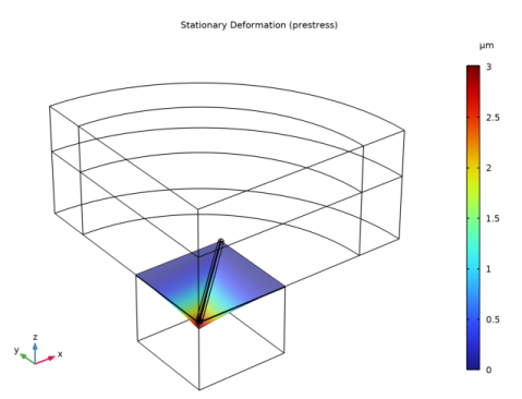
The stationary deformation should look like this. Note that the stationary deformation is only 3[um] at the center. The deformation is small compared to the total membrane thickness of 17[um]. This indicates that the effects of topology changes, captured by the introduction of a Moving Mesh feature, can be disregarded.
On-Axis Response at 10 cm
1
In the Home toolbar, click  Add Plot Group and choose 1D Plot Group.
2
In the Settings window for 1D Plot Group, type On-Axis Response at 10 cm in the Label text field.
3
Click to expand the Title section. From the Title type list, choose Label.
Octave Band 1
1
In the On-Axis Response at 10 cm toolbar, click  More Plots and choose Octave Band.
2
In the Settings window for Octave Band, locate the Selection section.
3
From the Geometric entity level list, choose Global.
4
Locate the y-Axis Data section. In the Expression text field, type pext(0,0,10[cm]).
5
Locate the Plot section. From the Quantity list, choose Continuous power spectral density.
6
In the On-Axis Response at 10 cm toolbar, click  Plot.
The on-axis response, 10 cm above the speaker, should look like this.
Appendix: Geometry Sequence Instructions
From the File menu, choose New.
New
In the New window, click  Model Wizard.
Model Wizard
1
In the Model Wizard window, click  3D.
2
Geometry 1
Adjust the units of the model to µm.
1
In the Model Builder window, under Component 1 (comp1) click Geometry 1.
2
In the Settings window for Geometry, locate the Units section.
3
From the Length unit list, choose µm.
Import the parameters from an external file. This file contains parameters like dimensions, maximum frequency and voltage that define the current model.
Global Definitions
Parameters 1
1
In the Model Builder window, under Global Definitions click Parameters 1.
2
In the Settings window for Parameters, locate the Parameters section.
3
Create a Work Plane where the main features of the speaker will be defined. The model uses symmetry to only model one fourth of the geometry. This reduces the computation time.
Geometry 1
Click the  Show Grid button in the Graphics toolbar.
Work Plane 1 (wp1)
In the Geometry toolbar, click  Work Plane.
Work Plane 1 (wp1)>Plane Geometry
In the Model Builder window, click Plane Geometry.
Work Plane 1 (wp1)>Square 1 (sq1)
1
In the Work Plane toolbar, click  Square.
2
In the Settings window for Square, locate the Size section.
3
In the Side length text field, type l_speaker/2.
4
Click  Build Selected.
5
Click the  Zoom Extents button in the Graphics toolbar.
Work Plane 1 (wp1)>Rectangle 1 (r1)
1
In the Work Plane toolbar, click  Rectangle.
Create a rectangle that represents the air gap in the membrane. This gap will be modeled using Thermoviscous Acoustics.
2
In the Settings window for Rectangle, locate the Size and Shape section.
3
In the Width text field, type sqrt(2)/2*l_speaker-air_gap.
4
In the Height text field, type 12*air_gap.
5
Locate the Position section. From the Base list, choose Center.
6
In the xw text field, type l_speaker/4.
7
In the yw text field, type l_speaker/4.
8
Locate the Rotation Angle section. In the Rotation text field, type 45.
9
Click to expand the Layers section. In the table, enter the following settings:
10
Select the Layers on top check box.
11
Click  Build Selected.
Create a new rectangle so that a swept mesh can be generated in the Thermoviscous Acoustics domains.
Work Plane 1 (wp1)>Rectangle 2 (r2)
1
In the Work Plane toolbar, click  Rectangle.
2
In the Settings window for Rectangle, locate the Size and Shape section.
3
In the Width text field, type sqrt(2)/2*l_speaker-16*air_gap.
4
In the Height text field, type 12*air_gap.
5
Locate the Position section. From the Base list, choose Center.
6
In the xw text field, type l_speaker/4.
7
In the yw text field, type l_speaker/4.
8
Locate the Rotation Angle section. In the Rotation text field, type 45.
Work Plane 1 (wp1)>Union 1 (uni1)
1
In the Work Plane toolbar, click  Booleans and Partitions and choose Union.
2
Click in the Graphics window and then press Ctrl+A to select all objects.
3
In the Settings window for Union, click  Build Selected.
Work Plane 1 (wp1)>Delete Entities 1 (del1)
1
Right-click Plane Geometry and choose Delete Entities.
2
In the Settings window for Delete Entities, locate the Entities or Objects to Delete section.
3
From the Geometric entity level list, choose Domain.
4
On the object uni1, select Domains 1, 6, 13, and 17 only.
5
Click  Build Selected.
Extrude the Work Plane 1 to create the 3D geometry that represents the silicon and the PZT Layers of the membrane.
Extrude 1 (ext1)
1
In the Model Builder window, under Component 1 (comp1)>Geometry 1 right-click Work Plane 1 (wp1) and choose Extrude.
2
In the Settings window for Extrude, locate the Distances section.
3
4
Select the Reverse direction check box.
5
Click  Build Selected.
The geometry should look like this.
Add a cylinder that will be used for the Thermoviscous Acoustics domains.
Cylinder 1 (cyl1)
1
In the Geometry toolbar, click  Cylinder.
2
In the Settings window for Cylinder, locate the Size and Shape section.
3
In the Radius text field, type 6*air_gap.
4
In the Height text field, type sqrt(2)/2*l_speaker.
5
Locate the Axis section. From the Axis type list, choose Cartesian.
6
In the x text field, type 1.
7
In the y text field, type 1.
8
In the z text field, type 0.
9
Click to expand the Layers section. In the table, enter the following settings:
10
Clear the Layers on side check box.
11
Select the Layers on bottom check box.
12
Select the Layers on top check box.
13
Click  Build Selected.
Split the cylinder in two halves and move them to the right location in the following steps.
Partition Objects 1 (par1)
1
In the Geometry toolbar, click  Booleans and Partitions and choose Partition Objects.
2
3
In the Settings window for Partition Objects, locate the Partition Objects section.
4
From the Partition with list, choose Work plane.
5
Click  Build Selected.
Move 1 (mov1)
1
In the Geometry toolbar, click  Transforms and choose Move.
2
3
In the Settings window for Move, locate the Displacement section.
4
In the z text field, type -th_pzt-th_si.
5
Locate the Input section. Select the Keep input objects check box.
6
Click  Build Selected.
Delete Entities 1 (del1)
1
In the Model Builder window, right-click Geometry 1 and choose Delete Entities.
2
In the Settings window for Delete Entities, locate the Entities or Objects to Delete section.
3
From the Geometric entity level list, choose Domain.
4
On the object mov1, select Domains 2, 4, and 6 only.
5
On the object par1, select Domains 1, 3, and 5 only.
6
Click  Build Selected.
Add a cylinder that represents an infinite domain in front of the speaker.
Cylinder 2 (cyl2)
1
In the Geometry toolbar, click  Cylinder.
2
In the Settings window for Cylinder, locate the Size and Shape section.
3
In the Radius text field, type 1.2*l_speaker.
4
In the Height text field, type 1.2*l_speaker.
5
Locate the Position section. In the z text field, type -0.6*l_speaker.
6
Locate the Layers section. In the table, enter the following settings:
7
Select the Layers on bottom check box.
8
Select the Layers on top check box.
9
Click  Build Selected.
10
Click the  Wireframe Rendering button in the Graphics toolbar.
Wireframe Rendering simplifies the selection of boundaries in the geometry.
Partition Objects 2 (par2)
1
In the Geometry toolbar, click  Booleans and Partitions and choose Partition Objects.
2
3
In the Settings window for Partition Objects, locate the Partition Objects section.
4
From the Partition with list, choose Work plane.
5
Click  Build Selected.
Delete Entities 2 (del2)
1
Right-click Geometry 1 and choose Delete Entities.
2
In the Settings window for Delete Entities, locate the Entities or Objects to Delete section.
3
From the Geometric entity level list, choose Domain.
4
On the object par2, select Domains 1–4, 9, 10, 13, 14, 17, and 18 only.
5
Click  Build Selected.
Block 1 (blk1)
1
In the Geometry toolbar, click  Block.
This block represents the back volume of the speaker.
2
In the Settings window for Block, locate the Size and Shape section.
3
In the Width text field, type l_speaker/2.
4
In the Depth text field, type l_speaker/2.
5
In the Height text field, type d_speaker.
6
Locate the Position section. In the z text field, type -th_si-th_pzt-d_speaker.
7
Click  Build Selected.
Work Plane 2 (wp2)
1
In the Geometry toolbar, click  Work Plane.
This is the first symmetry plane.
2
In the Settings window for Work Plane, locate the Plane Definition section.
3
From the Plane list, choose yz-plane.
Work Plane 3 (wp3)
1
In the Geometry toolbar, click  Work Plane.
This is the second symmetry plane.
2
In the Settings window for Work Plane, locate the Plane Definition section.
3
From the Plane list, choose zx-plane.
Union 1 (uni1)
1
In the Geometry toolbar, click  Booleans and Partitions and choose Union.
2
3
Click in the Graphics window and then press Ctrl+A to select all objects.
4
In the Settings window for Union, click  Build Selected.
Partition Objects 3 (par3)
1
In the Geometry toolbar, click  Booleans and Partitions and choose Partition Objects.
2
3
In the Settings window for Partition Objects, locate the Partition Objects section.
4
From the Partition with list, choose Work plane.
5
From the Work plane list, choose Work Plane 2 (wp2).
6
Click  Build Selected.
Partition Objects 4 (par4)
1
In the Geometry toolbar, click  Booleans and Partitions and choose Partition Objects.
2
3
In the Settings window for Partition Objects, locate the Partition Objects section.
4
From the Partition with list, choose Work plane.
5
Click  Build Selected.
Delete Entities 3 (del3)
1
Right-click Geometry 1 and choose Delete Entities.
Delete the domains outside of the first quadrant xy-plane.
2
In the Settings window for Delete Entities, locate the Entities or Objects to Delete section.
3
From the Geometric entity level list, choose Domain.
4
On the object par4, select Domains 1–14, 17, 21, 48, and 55 only.
5
Click  Build Selected.
6
Click the  Zoom Extents button in the Graphics toolbar.
The geometry should look like this.
Thermoviscous Domain 1
1
In the Geometry toolbar, click  Selections and choose Cylinder Selection.
This selection includes the domains that will be represented using the Thermoviscous Acoustics, Frequency Domain interface.
2
In the Settings window for Cylinder Selection, type Thermoviscous Domain 1 in the Label text field.
3
Locate the Size and Shape section. In the Outer radius text field, type 6*air_gap.
4
Locate the Axis section. From the Axis type list, choose Cartesian.
5
In the x text field, type 1.
6
In the y text field, type 1.
7
In the z text field, type 0.
8
Locate the Output Entities section. From the Include entity if list, choose All vertices inside cylinder.
Thermoviscous Domain 2
1
Right-click Thermoviscous Domain 1 and choose Duplicate.
2
In the Settings window for Cylinder Selection, type Thermoviscous Domain 2 in the Label text field.
3
Locate the Position section. In the z text field, type -th_si-th_pzt.
4
Click  Build Selected.
Thermoviscous Domains
1
In the Geometry toolbar, click  Selections and choose Union Selection.
2
In the Settings window for Union Selection, type Thermoviscous Domains in the Label text field.
3
Locate the Input Entities section. Click  Add.
4
In the Add dialog box, in the Selections to add list, choose Thermoviscous Domain 1 and Thermoviscous Domain 2.
5
6
In the Settings window for Union Selection, locate the Color section.
7
From the Color list, choose Color 5.
Silicon Layer With Air
1
In the Geometry toolbar, click  Selections and choose Box Selection.
2
In the Settings window for Box Selection, type Silicon Layer With Air in the Label text field.
3
Locate the Box Limits section. In the z minimum text field, type -th_si.
4
In the z maximum text field, type 0.
5
Locate the Output Entities section. From the Include entity if list, choose Entity inside box.
PZT Layer With Air
1
In the Geometry toolbar, click  Selections and choose Box Selection.
2
In the Settings window for Box Selection, type PZT Layer With Air in the Label text field.
3
Locate the Box Limits section. In the z minimum text field, type -th_si-th_pzt.
4
In the z maximum text field, type -th_si.
5
Locate the Output Entities section. From the Include entity if list, choose Entity inside box.
Silicon Domains
1
In the Geometry toolbar, click  Selections and choose Difference Selection.
2
In the Settings window for Difference Selection, type Silicon Domains in the Label text field.
3
Locate the Input Entities section. Click  Add.
4
In the Add dialog box, select Silicon Layer With Air in the Selections to add list.
5
6
In the Settings window for Difference Selection, locate the Input Entities section.
7
8
In the Add dialog box, select Thermoviscous Domains in the Selections to subtract list.
9
10
In the Settings window for Difference Selection, locate the Color section.
11
From the Color list, choose Color 8.
12
Click  Build Selected.
PZT Domains
1
In the Geometry toolbar, click  Selections and choose Difference Selection.
2
In the Settings window for Difference Selection, type PZT Domains in the Label text field.
3
Locate the Input Entities section. Click  Add.
4
In the Add dialog box, select PZT Layer With Air in the Selections to add list.
5
6
In the Settings window for Difference Selection, locate the Input Entities section.
7
8
In the Add dialog box, select Thermoviscous Domains in the Selections to subtract list.
9
10
In the Settings window for Difference Selection, locate the Color section.
11
From the Color list, choose Color 12.
Structural Domains
1
In the Geometry toolbar, click  Selections and choose Union Selection.
2
In the Settings window for Union Selection, type Structural Domains in the Label text field.
3
Locate the Input Entities section. Click  Add.
4
In the Add dialog box, in the Selections to add list, choose Silicon Domains and PZT Domains.
5
All Domains
1
In the Geometry toolbar, click  Selections and choose Ball Selection.
2
In the Settings window for Ball Selection, type All Domains in the Label text field.
3
Locate the Ball Radius section. In the Radius text field, type 2*l_speaker.
4
Click  Build Selected.
Inner Domains
1
In the Geometry toolbar, click  Selections and choose Cylinder Selection.
2
In the Settings window for Cylinder Selection, type Inner Domains in the Label text field.
3
Locate the Size and Shape section. In the Outer radius text field, type 0.8*l_speaker.
4
In the Top distance text field, type 0.3*l_speaker.
5
Click  Build Selected.
PML Domains
1
In the Geometry toolbar, click  Selections and choose Difference Selection.
2
In the Settings window for Difference Selection, type PML Domains in the Label text field.
3
Locate the Input Entities section. Click  Add.
4
In the Add dialog box, select All Domains in the Selections to add list.
5
6
In the Settings window for Difference Selection, locate the Input Entities section.
7
8
In the Add dialog box, select Inner Domains in the Selections to subtract list.
9
10
In the Settings window for Difference Selection, click  Build Selected.
11
Click  Build Selected.
Pressure Acoustics Domains
1
In the Geometry toolbar, click  Selections and choose Difference Selection.
2
In the Settings window for Difference Selection, type Pressure Acoustics Domains in the Label text field.
3
Locate the Input Entities section. Click  Add.
4
In the Add dialog box, select All Domains in the Selections to add list.
5
6
In the Settings window for Difference Selection, locate the Input Entities section.
7
8
In the Add dialog box, in the Selections to subtract list, choose Thermoviscous Domains and Structural Domains.
9
10
In the Settings window for Difference Selection, locate the Color section.
11
From the Color list, choose Color 10.
12
Click  Build Selected.
Electrostatics Domains
1
In the Geometry toolbar, click  Selections and choose Union Selection.
2
In the Settings window for Union Selection, type Electrostatics Domains in the Label text field.
3
Locate the Input Entities section. Click  Add.
4
In the Add dialog box, in the Selections to add list, choose Thermoviscous Domains and Structural Domains.
5
Air Domains
1
In the Geometry toolbar, click  Selections and choose Union Selection.
2
In the Settings window for Union Selection, type Air Domains in the Label text field.
3
Locate the Input Entities section. Click  Add.
4
In the Add dialog box, in the Selections to add list, choose Thermoviscous Domains and Pressure Acoustics Domains.
5
All Boundaries
1
In the Geometry toolbar, click  Selections and choose Box Selection.
2
In the Settings window for Box Selection, type All Boundaries in the Label text field.
3
Locate the Geometric Entity Level section. From the Level list, choose Boundary.
Non Symmetric Boundaries
1
In the Geometry toolbar, click  Selections and choose Box Selection.
2
In the Settings window for Box Selection, type Non Symmetric Boundaries in the Label text field.
3
Locate the Geometric Entity Level section. From the Level list, choose Boundary.
4
Locate the Box Limits section. In the x minimum text field, type 0.01.
5
In the y minimum text field, type 0.01.
Symmetric Boundaries
1
In the Geometry toolbar, click  Selections and choose Difference Selection.
2
In the Settings window for Difference Selection, type Symmetric Boundaries in the Label text field.
3
Locate the Geometric Entity Level section. From the Level list, choose Boundary.
4
Locate the Input Entities section. Click  Add.
5
In the Add dialog box, select All Boundaries in the Selections to add list.
6
7
In the Settings window for Difference Selection, locate the Input Entities section.
8
9
In the Add dialog box, select Non Symmetric Boundaries in the Selections to subtract list.
10
Exterior Field Boundaries
1
In the Geometry toolbar, click  Selections and choose Explicit Selection.
2
In the Settings window for Explicit Selection, type Exterior Field Boundaries in the Label text field.
3
Locate the Entities to Select section. From the Geometric entity level list, choose Boundary.
4
On the object del3, select Boundaries 23 and 49 only.
Ground
1
In the Geometry toolbar, click  Selections and choose Explicit Selection.
2
In the Settings window for Explicit Selection, type Ground in the Label text field.
3
Locate the Entities to Select section. From the Geometric entity level list, choose Boundary.
4
On the object del3, select Boundaries 33, 42, 62, 71, 89, 96, 107, and 129 only.
Terminal
1
In the Geometry toolbar, click  Selections and choose Explicit Selection.
2
In the Settings window for Explicit Selection, type Terminal in the Label text field.
3
Locate the Entities to Select section. From the Geometric entity level list, choose Boundary.
4
On the object del3, select Boundaries 28, 39, 59, 67, 86, 93, 102, and 126 only.
All except PML
1
In the Geometry toolbar, click  Selections and choose Complement Selection.
2
In the Settings window for Complement Selection, type All except PML in the Label text field.
3
Locate the Input Entities section. Click  Add.
4
In the Add dialog box, select PML Domains in the Selections to invert list.
5