|
|
•
|
Reflective (or reactive) mufflers — those that reflect acoustic waves by abrupt area expansions or changes of impedance.
|
|
•
|
Dissipative mufflers — mufflers based on dissipation of acoustic energy into heat through viscous and thermal losses in fibrous materials or flow-related (resistive) losses in perforated pipes.
|
|
•
|


|
1
|
|
2
|
In the Select Physics tree, select Acoustics>Pressure Acoustics>Pressure Acoustics, Frequency Domain (acpr).
|
|
3
|
Click Add.
|
|
4
|
Click
|
|
5
|
|
6
|
Click
|
|
1
|
|
2
|
Browse to the model’s Application Libraries folder and double-click the file perforated_muffler_geom_sequence.mph.
|
|
3
|
|
1
|
|
2
|
|
1
|
|
2
|
|
3
|
|
4
|
Click
|
|
5
|
Browse to the model’s Application Libraries folder and double-click the file perforated_muffler_exp_data.txt.
|
|
6
|
Click
|
|
7
|
|
1
|
|
2
|
|
1
|
|
2
|
|
3
|
In the tree, select Built-in>Air.
|
|
4
|
|
5
|
|
1
|
In the Model Builder window, under Component 1 (comp1) right-click Pressure Acoustics, Frequency Domain (acpr) and choose Interior Conditions>Interior Sound Hard Boundary (Wall).
|
|
2
|
In the Settings window for Interior Sound Hard Boundary (Wall), locate the Boundary Selection section.
|
|
3
|
|
1
|
|
2
|
|
3
|
|
4
|
|
5
|
|
6
|
|
7
|
|
1
|
|
2
|
|
3
|
|
4
|
|
5
|
|
6
|
|
7
|
|
8
|
|
9
|
|
1
|
|
2
|
|
3
|
|
4
|
|
5
|
|
6
|
|
7
|
|
1
|
|
2
|
|
3
|
|
4
|
|
5
|
|
6
|
|
7
|
|
1
|
|
2
|
|
3
|
|
4
|
|
5
|
|
1
|
|
2
|
|
3
|
|
1
|
|
2
|
|
3
|
|
4
|
|
1
|
|
2
|
|
3
|
|
1
|
|
2
|
|
3
|
|
1
|
|
2
|
|
3
|
|
1
|
|
2
|
|
3
|
|
5
|
|
1
|
|
2
|
|
3
|
|
1
|
|
2
|
|
3
|
|
4
|
|
1
|
|
2
|
|
1
|
|
2
|
|
3
|
|
1
|
|
2
|
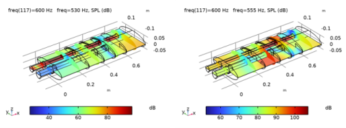
In the Settings window for Slice, click Replace Expression in the upper-right corner of the Expression section. From the menu, choose Component 1 (comp1)>Pressure Acoustics, Frequency Domain>Pressure and sound pressure level>acpr.Lp_t - Total sound pressure level - dB.
|
|
3
|
|
4
|
|
5
|
|
1
|
|
2
|
|
3
|
|
4
|
|
5
|
|
1
|
|
2
|
|
3
|
|
4
|
|
5
|
|
6
|
|
7
|
|
8
|
|
9
|
|
10
|
|
1
|
|
2
|
|
3
|
|
4
|
|
1
|
|
2
|
|
3
|
|
4
|
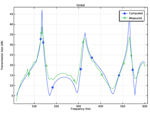
In the associated text field, type Frequency (Hz).
|
|
5
|
|
6
|
In the associated text field, type Transmission loss (dB).
|
|
1
|
|
2
|
|
4
|
Click to expand the Coloring and Style section. Find the Line markers subsection. From the Marker list, choose Cycle.
|
|
5
|
|
7
|
|
1
|
|
2
|
|
3
|
|
1
|
|
2
|
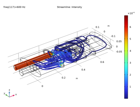
In the Settings window for Streamline, click Replace Expression in the upper-right corner of the Expression section. From the menu, choose Component 1 (comp1)>Pressure Acoustics, Frequency Domain>Intensity>acpr.Ix,acpr.Iy,acpr.Iz - Intensity.
|
|
3
|
Locate the Coloring and Style section. Find the Line style subsection. From the Type list, choose Tube.
|
|
1
|
|
2
|
In the Settings window for Color Expression, click Replace Expression in the upper-right corner of the Expression section. From the menu, choose Component 1 (comp1)>Pressure Acoustics, Frequency Domain>Intensity>acpr.I_mag - Intensity magnitude - W/m².
|
|
3
|
|
1
|
|
2
|
|
3
|
|
1
|
|
2
|
|
3
|
|
4
|
|
5
|
|
1
|
In the Model Builder window, under Component 1 (comp1)>Geometry 1 right-click Work Plane 1 (wp1) and choose Extrude.
|
|
2
|
|
1
|
|
2
|
|
3
|
|
4
|
|
5
|
|
1
|
|
2
|
|
3
|
|
4
|
|
5
|
|
1
|
|
2
|
|
3
|
|
4
|
|
5
|
|
1
|
In the Model Builder window, under Component 1 (comp1)>Geometry 1 right-click Work Plane 2 (wp2) and choose Extrude.
|
|
2
|
|
3
|
In the list, select wp2.c2.
|
|
4
|
|
5
|
Select the object wp2.c1 only.
|
|
6
|
Locate the Distances section. In the table, enter the following settings:
|
|
1
|
|
2
|
|
4
|
|
1
|
|
2
|
|
3
|
|
4
|
On the object ext1, select Boundaries 18, 13, 8, 3, 5, 10, 15, and 20 only.
|
|
5
|
|
6
|
|
7
|
|
8
|
On the object ext1, select Boundary 6 only.
|
|
1
|
|
2
|
|
3
|
|
4
|
In the xw text field, type -117[mm] -137.5[mm] -137.5[mm] -117[mm] -108[mm] -96.5[mm] -96.5[mm] -117[mm].
|
|
5
|
|
1
|
|
2
|
On the object pol1, select Points 2 and 7 only.
|
|
3
|
|
4
|
|
1
|
|
2
|
|
3
|
|
4
|
In the xw text field, type 136.5[mm] 136.5[mm] 136.5[mm] 131[mm] 131[mm] 121[mm] 121[mm] 113.5[mm] 113.5[mm] 105.5[mm] 105.5[mm] 97.3[mm] 97.3[mm] 90[mm] 90[mm] 80.8[mm] 80.8[mm] 72.4[mm] 72.4[mm] 72.4[mm] 72.4[mm] 60[mm] 60[mm] 55[mm] 55[mm] 45.9[mm] 45.9[mm] 37[mm] 37[mm] 28[mm] 28[mm] 28[mm] 28[mm] 37[mm] 37[mm] 45.9[mm] 45.9[mm] 55[mm] 55[mm] 63.8[mm] 63.8[mm] 72.4[mm] 72.4[mm] 80.8[mm] 80.8[mm] 89[mm] 89[mm] 97.3[mm] 97.3[mm] 105.5[mm] 105.5[mm] 113.5[mm] 113.5[mm] 121[mm] 121[mm] 126[mm] 126[mm] 123.3[mm] 123.3[mm] 123.3[mm] 123.3[mm] 136.5[mm] .
|
|
5
|
In the yw text field, type -25[mm] -20.5[mm] -20.5[mm] -12.2[mm] -12.2[mm] -4[mm] -4[mm] -0.1[mm] -0.1[mm] 3.3[mm] 3.3[mm] 6[mm] 6[mm] 8[mm] 8[mm] 10.3[mm] 10.3[mm] 12[mm] 12[mm] 12[mm] 12[mm] 14[mm] 14[mm] 15[mm] 15[mm] 15.7[mm] 15.7[mm] 16.8[mm] 16.8[mm] 17.5[mm] 17.5[mm] 12.5[mm] 12.5[mm] 11.8[mm] 11.8[mm] 10.7[mm] 10.7[mm] 10[mm] 10[mm] 8.5[mm] 8.5[mm] 7[mm] 7[mm] 5.3[mm] 5.3[mm] 3.5[mm] 3.5[mm] 1[mm] 1[mm] -1.7[mm] -1.7[mm] -5.1[mm] -5.1[mm] -9[mm] -9[mm] -12.2[mm] -12.2[mm] -20.5[mm] -20.5[mm] -25[mm] -25[mm] -25[mm] .
|
|
1
|
In the Model Builder window, under Component 1 (comp1)>Geometry 1 right-click Work Plane 3 (wp3) and choose Work Plane.
|
|
2
|
|
3
|
|
4
|
|
5
|
On the object ext1, select Boundary 11 only.
|
|
6
|
In the tree, select ext1.
|
|
1
|
|
2
|
|
3
|
|
4
|
In the xw text field, type -137.5[mm] -137.5[mm] -135[mm] -117[mm] -108[mm] -96.5[mm] -90[mm] -81[mm] -69.5[mm] -63[mm] -60.5[mm] -63[mm] -63[mm] -69.5[mm] -69.5[mm] -96.5[mm] -117[mm] -137.5[mm].
|
|
5
|
In the yw text field, type -25[mm] -13.5[mm] -13.5[mm] -13.5[mm] -4.5[mm] -4.5[mm] -4.5[mm] 4.5[mm] 4.5[mm] 4.5[mm] 2[mm] -0.5[mm] -3.5[mm] -9[mm] -25[mm] -25[mm] -25[mm] -25[mm].
|
|
1
|
|
2
|
|
3
|
|
4
|
In the xw text field, type 136.5[mm] 136.5[mm] 136.5[mm] 131[mm] 131[mm] 121[mm] 121[mm] 113.5[mm] 113.5[mm] 105.5[mm] 105.5[mm] 97.3[mm] 97.3[mm] 90[mm] 90[mm] 80.8[mm] 80.8[mm] 72.4[mm] 72.4[mm] 72.4[mm] 72.4[mm] 60[mm] 60[mm] 55[mm] 55[mm] 45.9[mm] 45.9[mm] 37[mm] 37[mm] 28[mm] 28[mm] 28[mm] 28[mm] 37[mm] 37[mm] 45.9[mm] 45.9[mm] 55[mm] 55[mm] 63.8[mm] 63.8[mm] 72.4[mm] 72.4[mm] 80.8[mm] 80.8[mm] 89[mm] 89[mm] 97.3[mm] 97.3[mm] 105.5[mm] 105.5[mm] 113.5[mm] 113.5[mm] 121[mm] 121[mm] 126[mm] 126[mm] 123.3[mm] 123.3[mm] 123.3[mm] 123.3[mm] 136.5[mm] .
|
|
5
|
In the yw text field, type -25[mm] -20.5[mm] -20.5[mm] -12.2[mm] -12.2[mm] -4[mm] -4[mm] -0.1[mm] -0.1[mm] 3.3[mm] 3.3[mm] 6[mm] 6[mm] 8[mm] 8[mm] 10.3[mm] 10.3[mm] 12[mm] 12[mm] 12[mm] 12[mm] 14[mm] 14[mm] 15[mm] 15[mm] 15.7[mm] 15.7[mm] 16.8[mm] 16.8[mm] 17.5[mm] 17.5[mm] 12.5[mm] 12.5[mm] 11.8[mm] 11.8[mm] 10.7[mm] 10.7[mm] 10[mm] 10[mm] 8.5[mm] 8.5[mm] 7[mm] 7[mm] 5.3[mm] 5.3[mm] 3.5[mm] 3.5[mm] 1[mm] 1[mm] -1.7[mm] -1.7[mm] -5.1[mm] -5.1[mm] -9[mm] -9[mm] -12.2[mm] -12.2[mm] -20.5[mm] -20.5[mm] -25[mm] -25[mm] -25[mm] .
|
|
1
|
|
2
|
Select the object wp4 only.
|
|
3
|
|
4
|
|
1
|
|
2
|
Select the object wp4 only.
|
|
3
|
|
4
|
|
1
|
|
2
|
On the object copy2, select Boundary 2 only.
|
|
3
|
|
1
|
|
2
|
|
3
|
|
4
|
|
1
|
|
2
|
|
1
|
|
2
|
Select the object uni2 only.
|
|
3
|
|
4
|
|
5
|
|
6
|
Select the object uni1 only.
|
|
7
|
|
1
|
|
2
|
|
1
|
|
2
|
|
3
|
|
4
|
On the object fin, select Boundary 6 only.
|
|
1
|
|
2
|
|
3
|
|
4
|
On the object fin, select Boundary 1 only.
|
|
1
|
|
2
|
|
3
|
|
4
|
On the object fin, select Boundaries 50, 52, 74, and 76 only.
|
|
1
|
|
2
|
In the Settings window for Explicit Selection, type Pipe Perforate with Sleeve in the Label text field.
|
|
3
|
|
4
|
On the object fin, select Boundaries 26 and 28 only.
|
|
1
|
|
2
|
In the Settings window for Explicit Selection, type Inlet Baffle Perforates in the Label text field.
|
|
3
|
|
4
|
On the object fin, select Boundaries 43, 67, and 91 only.
|
|
1
|
|
2
|
In the Settings window for Explicit Selection, type Outlet Baffle Perforates in the Label text field.
|
|
3
|
|
4
|
On the object fin, select Boundaries 36, 60, 84, and 101 only.
|
|
1
|
|
2
|
|
3
|
|
4
|
On the object fin, select Boundaries 97 and 108 only.
|
|
1
|
|
2
|
|
3
|
|
4
|
Select the object fin only.
|
|
1
|
|
2
|
|
3
|
Click
|
|
4
|
|
5
|
Click OK.
|
|
6
|
|
7
|
|
8
|
|
9
|
|
1
|
|
2
|
|
3
|
|
4
|
|
5
|
|
6
|
Click OK.
|
|
7
|
|
8
|
Click
|
|
9
|
In the Add dialog box, in the Selections to subtract list, choose Pipe Perforates, Pipe Perforate with Sleeve, Inlet Baffle Perforates, Outlet Baffle Perforates, and Pipe Ends.
|
|
10
|
Click OK.
|
|
11
|
|
1
|
|
2
|
|
3
|
|
4
|
|
5
|
|
1
|
|
2
|