PDF

Angle Beam Nondestructive Testing
Introduction
Angle beam ultrasonic units are used for nondestructive testing (NDT) of solid objects, such as metal pipes. They are especially useful for detecting flaws in and around welding areas, such as pores, small cracks, lack of fusion, and so on. Angle beam NDT is often used where the straight beam testing struggles to find defects, for example, when the cracks are vertical and thin and thus not detectable because of small amount of reflection. The operating principle of angle beam NDT lies in the conversion of a longitudinal (compression) wave sent by the transducer into a refracted shear (transverse) wave in the test sample. The shear wave is then reflected by the flaws in the test object. Compared to longitudinal waves, shear waves have lower attenuation and shorter wavelength, which makes them capable of detecting smaller defects.
In this tutorial, the Elastic Waves, Time Explicit physics interfaces is used to model wave propagation in linear elastic media. The interface solves the linear elastic wave equation written in the velocity-strain form using the discontinuous Galerkin finite element method (dG-FEM) and an explicit time integration scheme. This approach is well suited for solving large-scale transient problems. The piezoelectric part of the transducer is modeled with the Piezoelectric Effect, Time Explicit multiphysics feature that couples the Elastic Waves, Time Explicit and the Electrostatics physics interfaces. The model takes advantage of a geometry assembly and a nonconforming mesh.
Model Definition
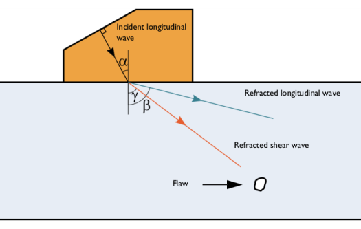
The angle beam transducers are designed to generate a refracted shear wave in the test sample that propagates at a certain angle to the sample surface, typically, from 40° to 70°. The angle or refraction depends on the material properties of the pair transducer wedge/test sample and the angle of incidence of the ultrasonic signal. The incident longitudinal wave that passes through the wedge with the speed cp1 results in refracted longitudinal and shear waves that propagate in the test sample with the speeds cp2 and cs2, respectively (see Figure 1). The angles of refraction are defined according to Snell’s law as
The first and the second critical angles are those which yield β = 90° and γ = 90°, respectively. For the pair of plastic wedge with cp1 = 2080 m/s and aluminum test object with cp2 = 6200 m/s and cs2 = 3120 m/s, this yields the first and the second critical angles of about 19.5° and 44.7°, respectively. In this tutorial, the shear wave refraction angle is γ = 45°, which results in the angle of incidence α = 28°. The angle of incidence lies between the first and the second critical angles and therefore a refracted longitudinal wave will skim along the surface of the test sample.
Figure 1: Wave refraction at the wedge/test sample boundary
The angle beam NDT units usually operate at frequencies between 1 and 10 MHz. The unit is driven by voltage signal applied to the piezoelectric transducer. In this tutorial, the center frequency of the signal f0 = 1 MHz. The transducer is attached to the wedge via a matching layer. The transducer and the matching layer are half and one-quarter wavelength thick, respectively. The transducer is surrounded by a backing layer block (also called damping block) at the back. The main parts of the setup are shown in Figure 2.
The matching layer and the damping block materials should be chosen in such a way that the acoustic impedance of the former is close to that of the transducer, while the impedance of the latter is close to the geometric mean of those of the transducer and the wedge. That is,
.
Typical materials used for the matching and backing layers are alumina/epoxy or tungsten/epoxy composites. The desired acoustical properties are achieved by the amount of the alumina or tungsten powder in the composite. The elastic properties of such a two-phase composite may be defined based on the Devaney model (see Ref. 1). The properties of the angle beam unit components used in this model are listed in Table 1.
Figure 2: Angle beam NDT setup: test sample (yellow), wedge (orange), piezoelectric transducer (dark blue), matching (cyan) and backing (green) layers.
Results and Discussion
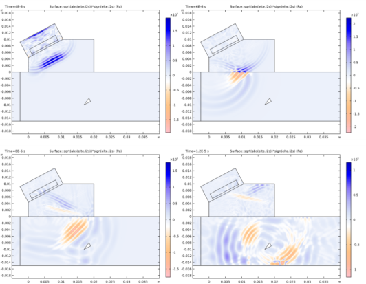
The evolution of the signal traveling from the transducer to the defect in the test sample is illustrated in Figure 3. Note that the longitudinal and shear waves are separated: the former are shown in blue and the latter, in orange. The longitudinal wave generated by the transducer travels through the wedge (t = 4 μs). Then the wave hits the surface of the test object and a refracted shear wave begins to propagate through it (t = 6 μs). The shear wave travels toward the defect (t = 8 μs), hits it and becomes reflected. The reflected wave travels back toward the testing unit (t = 12 μs).
Figure 3: Wave profiles at t = 4, 6, 8, and 12 μs.
Figure 4 shows the voltage signal on the transducer terminal for the test sample with defect on top of the reference signal recorded when the inspected object has no defects. The signals zoomed around the time when the reflected wave reached the transducer are depicted in Figure 5. It is seen that the received signal slowly starts to deviate from the reference soon after t = 15 μs, while the main portion of the reflected signal arrives at the transducer after t = 17 μs.
Figure 4: Voltage signal on the transducer terminal for the test samples with (green) and without (blue) the defect.
Figure 5: Voltage signal zoomed around the arrival time of the reflected wave.
Notes About the COMSOL Implementation
Geometry and Mesh
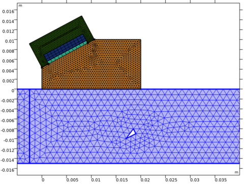
The model geometry is an assembly, which makes the parts of the geometry separated from one another and connected via Identity Boundary Pairs. The nodes of the generated mesh elements do not have to match on either side for the pairs thus making the mesh non-conformal. For wave propagation problems, feasible results are achieved when the mesh resolves the wavelengths of the propagating waves. The wavelength, in its turn, depends on the speed of sound in the material. Thus materials with lower speed of sound require finer mesh than those with higher speed of sound. The use of a non-conformal mesh in this tutorial makes it possible to reduce the number of DOFs solved for in the model. In this model, the mesh resolves the wavelength of the shear waves in each material, and it follows from Table 1 that one mesh element in the transducer domain corresponds to at least two mesh elements in the damping block domain on the other side of the pair as seen in Figure 6. The same is valid for the wedge/test sample pair..
Figure 6: Model mesh.
Reference
1. R.A. Webster, “Passive materials for high frequency piezocomposite ultrasonic transducers,” Ph.D. thesis, University of Birmingham, 2010.
Application Library path: Acoustics_Module/Ultrasound/angle_beam_ndt
Modeling Instructions
From the File menu, choose New.
New
In the New window, click  Model Wizard.
Model Wizard
1
In the Model Wizard window, click  2D.
2
Geometry 1
1
In the Geometry toolbar, click Insert Sequence and choose Insert Sequence.
2
3
In the Geometry toolbar, click  Build All.
Global Definitions
Geometry
1
In the Model Builder window, under Global Definitions click Parameters 1.
2
In the Settings window for Parameters, type Geometry in the Label text field.
Model Parameters
1
In the Home toolbar, click  Parameters and choose Add>Parameters.
2
In the Settings window for Parameters, locate the Parameters section.
3
Click  Load from File.
4
5
In the Label text field, type Model Parameters.
Create a voltage source given by a modulated Gaussian pulse with the center frequency f0.
Voltage Source
1
In the Home toolbar, click  Functions and choose Global>Analytic.
2
In the Settings window for Analytic, type Voltage Source in the Label text field.
3
In the Function name text field, type V0.
4
Locate the Definition section. In the Expression text field, type 100*exp(-((t - 2*T0)/(T0/2))^2)*sin(2*pi*f0*t).
5
In the Arguments text field, type t.
6
Locate the Units section. In the Function text field, type V.
7
8
Locate the Plot Parameters section. In the table, enter the following settings:
9
Click  Create Plot.
Results
Voltage Source
10
In the Settings window for 1D Plot Group, type Voltage Source in the Label text field.
Load the voltage signal received by the transducer when testing a sample without any defects.
Global Definitions
Interpolation 1 (int1)
1
In the Home toolbar, click  Functions and choose Global>Interpolation.
2
In the Settings window for Interpolation, locate the Definition section.
3
From the Data source list, choose File.
4
Click  Browse.
5
6
Find the Functions subsection. In the table, enter the following settings:
7
Locate the Interpolation and Extrapolation section. From the Extrapolation list, choose None.
8
Locate the Units section. In the Function table, enter the following settings:
9
In the Argument table, enter the following settings:
10
Click  Create Plot.
Results
Terminal Voltage
In the Settings window for 1D Plot Group, type Terminal Voltage in the Label text field.
Function 1
1
In the Model Builder window, expand the Terminal Voltage node, then click Function 1.
2
In the Settings window for Function, click to expand the Legends section.
3
Select the Show legends check box.
4
From the Legends list, choose Manual.
5
6
In the Terminal Voltage toolbar, click  Plot.
Create selections to simplify the model setup.
Definitions
Transducer
1
In the Definitions toolbar, click  Explicit.
2
3
In the Settings window for Explicit, type Transducer in the Label text field.
4
Locate the Color section. From the Color list, choose Color 5.
Matching Layer
1
In the Definitions toolbar, click  Explicit.
2
3
In the Settings window for Explicit, type Matching Layer in the Label text field.
4
Locate the Color section. From the Color list, choose Color 10.
Damping Block
1
In the Definitions toolbar, click  Explicit.
2
3
In the Settings window for Explicit, type Damping Block in the Label text field.
4
Locate the Color section. From the Color list, choose Color 9.
Wedge
1
In the Definitions toolbar, click  Explicit.
2
3
In the Settings window for Explicit, type Wedge in the Label text field.
4
Locate the Color section. From the Color list, choose Color 18.
Test Sample
1
In the Definitions toolbar, click  Explicit.
2
3
In the Settings window for Explicit, type Test Sample in the Label text field.
4
Locate the Color section. From the Color list, choose Color 4.
Add a coordinate system to align the piezoelectric crystal in such a way that its Z-axis is perpendicular to the transducer surface.
Transducer Coordinate System
1
In the Definitions toolbar, click  Coordinate Systems and choose Base Vector System.
2
In the Settings window for Base Vector System, locate the Base Vectors section.
3
From the Out-of-plane index list, choose 2.
4
5
Find the Simplifications subsection. Select the Assume orthonormal check box.
6
In the Label text field, type Transducer Coordinate System.
Create a view to zoom in on the area of the transducer and the defect.
View 2
1
In the Model Builder window, right-click Definitions and choose View.
2
In the Settings window for View, locate the View section.
3
Select the Lock axis check box.
Axis
1
In the Model Builder window, expand the View 2 node, then click Axis.
2
In the Settings window for Axis, locate the Axis section.
3
In the x minimum text field, type -0.005.
4
In the x maximum text field, type 0.04.
5
In the y minimum text field, type -0.012.
6
In the y maximum text field, type 0.012.
7
Click  Update.
The result should look like the one shown in Figure 2.
Now, proceed to setting up the physics. Note that the model geometry is an assembly and therefore each physics interface automatically imposes the Continuity boundary condition on all boundary pairs.
Component 1 (comp1)
In the Home toolbar, click  Windows and choose Add Physics.
Add Physics
1
Go to the Add Physics window.
2
In the tree, select Acoustics>Elastic Waves>Elastic Waves, Time Explicit (elte).
3
Click Add to Component 1 in the window toolbar.
Elastic Waves, Time Explicit (elte)
Elastic Waves, Time Explicit Model 1
1
In the Model Builder window, under Component 1 (comp1)>Elastic Waves, Time Explicit (elte) click Elastic Waves, Time Explicit Model 1.
2
In the Settings window for Elastic Waves, Time Explicit Model, locate the Linear Elastic Material section.
3
From the Specify list, choose Pressure-wave and shear-wave speeds.
Piezoelectric Material 1
1
In the Physics toolbar, click  Domains and choose Piezoelectric Material.
2
In the Settings window for Piezoelectric Material, locate the Domain Selection section.
3
From the Selection list, choose Transducer.
Low-Reflecting Boundary 1
1
In the Physics toolbar, click  Boundaries and choose Low-Reflecting Boundary.
2
Elastic Waves, Time Explicit Model 1
In the Model Builder window, click Elastic Waves, Time Explicit Model 1.
Damping 1
1
In the Physics toolbar, click  Attributes and choose Damping.
2
In the Settings window for Damping, locate the Domain Selection section.
3
From the Selection list, choose Matching Layer.
4
Locate the Damping Settings section. From the Input parameters list, choose Damping ratios.
5
In the f1 text field, type 0.99*f0.
6
In the ζ1 text field, type 5e-2.
7
In the f2 text field, type 1.01*f0.
8
In the ζ2 text field, type 5e-2.
Damping 2
1
Right-click Damping 1 and choose Duplicate.
2
In the Settings window for Damping, locate the Domain Selection section.
3
From the Selection list, choose Damping Block.
Damping 3
1
Right-click Damping 2 and choose Duplicate.
2
In the Settings window for Damping, locate the Domain Selection section.
3
From the Selection list, choose Wedge.
4
Locate the Damping Settings section. In the ζ1 text field, type 1e-2.
5
In the ζ2 text field, type 1e-2.
Damping 4
1
Right-click Damping 3 and choose Duplicate.
2
In the Settings window for Damping, locate the Domain Selection section.
3
From the Selection list, choose Test Sample.
4
Locate the Damping Settings section. In the ζ1 text field, type 0.5e-2.
5
In the ζ2 text field, type 0.5e-2.
Piezoelectric Material 1
1
In the Model Builder window, under Component 1 (comp1)>Elastic Waves, Time Explicit (elte) click Piezoelectric Material 1.
2
In the Settings window for Piezoelectric Material, locate the Coordinate System Selection section.
3
From the Coordinate system list, choose Transducer Coordinate System (sys2).
Mechanical Damping 1
1
In the Physics toolbar, click  Attributes and choose Mechanical Damping.
2
In the Settings window for Mechanical Damping, locate the Damping Settings section.
3
From the Input parameters list, choose Damping ratios.
4
In the f1 text field, type 0.99*f0.
5
In the ζ1 text field, type 0.5e-2.
6
In the f2 text field, type 1.01*f0.
7
In the ζ2 text field, type 0.5e-2.
Add Physics
1
Go to the Add Physics window.
2
In the tree, select AC/DC>Electric Fields and Currents>Electrostatics (es).
3
Click Add to Selection in the window toolbar.
Electrostatics (es)
1
In the Settings window for Electrostatics, locate the Domain Selection section.
2
From the Selection list, choose Transducer.
Charge Conservation, Piezoelectric 1
1
Right-click Component 1 (comp1)>Electrostatics (es) and choose Charge Conservation, Piezoelectric.
2
In the Settings window for Charge Conservation, Piezoelectric, locate the Domain Selection section.
3
From the Selection list, choose Transducer.
Ground 1
1
In the Physics toolbar, click  Boundaries and choose Ground.
2
Terminal 1
1
In the Physics toolbar, click  Boundaries and choose Terminal.
2
3
In the Settings window for Terminal, locate the Terminal section.
4
From the Terminal type list, choose Circuit.
Add Physics
1
Go to the Add Physics window.
2
In the tree, select AC/DC>Electrical Circuit (cir).
3
Click Add to Component 1 in the window toolbar.
Electrical Circuit (cir)
Voltage Source 1 (V1)
1
Right-click Component 1 (comp1)>Electrical Circuit (cir) and choose Voltage Source.
2
In the Settings window for Voltage Source, locate the Node Connections section.
3
4
Locate the Device Parameters section. In the vsrc text field, type V0(t).
Resistor 1 (R1)
1
In the Electrical Circuit toolbar, click  Resistor.
2
In the Settings window for Resistor, locate the Node Connections section.
3
4
Locate the Device Parameters section. In the R text field, type 2[ohm].
External I-terminal 1 (termI1)
1
In the Electrical Circuit toolbar, click  External I-terminal.
2
In the Settings window for External I-terminal, locate the Node Connections section.
3
In the Node name text field, type 2.
4
Locate the External Terminal section. From the V list, choose Terminal voltage (es/term1).
Multiphysics
Piezoelectric Effect, Time Explicit 1 (pzete1)
In the Model Builder window, under Component 1 (comp1) right-click Multiphysics and choose Piezoelectric Effect, Time Explicit.
Define a Global Variable Probe that will record the voltage signal at the terminal.
Definitions
Global Variable Probe 1 (var1)
1
In the Definitions toolbar, click  Probes and choose Global Variable Probe.
2
In the Settings window for Global Variable Probe, type V_with_defect in the Variable name text field.
3
Click Replace Expression in the upper-right corner of the Expression section. From the menu, choose Component 1 (comp1)>Electrostatics>Terminals>es.V0_1 - Terminal voltage - V.
4
Locate the Expression section. Select the Description check box.
5
Click to expand the Table and Window Settings section.
Add the absorbing layers (sponge layers) used to truncate the computational domain.
Absorbing Layer 1 (ab1)
1
In the Definitions toolbar, click  Absorbing Layer.
2
Now, set up the materials.
Materials
In the Home toolbar, click  Windows and choose Add Material from Library.
Add Material
1
Go to the Add Material window.
2
In the tree, select Built-in>Aluminum.
3
Click Add to Component in the window toolbar.
4
In the tree, select Built-in>Acrylic plastic.
5
Click Add to Component in the window toolbar.
Materials
Acrylic plastic (mat2)
1
In the Settings window for Material, locate the Geometric Entity Selection section.
2
From the Selection list, choose Wedge.
Add Material
1
Go to the Add Material window.
2
In the tree, select Built-in>Lead Zirconate Titanate (PZT-5H).
3
Click Add to Component in the window toolbar.
Materials
Lead Zirconate Titanate (PZT-5H) (mat3)
1
In the Settings window for Material, locate the Geometric Entity Selection section.
2
From the Selection list, choose Transducer.
Matching Material
1
In the Model Builder window, right-click Materials and choose Blank Material.
2
In the Settings window for Material, locate the Geometric Entity Selection section.
3
From the Selection list, choose Matching Layer.
4
Locate the Material Contents section. In the table, enter the following settings:
5
In the Label text field, type Matching Material.
Damping Material
1
Right-click Materials and choose Blank Material.
2
In the Settings window for Material, locate the Geometric Entity Selection section.
3
From the Selection list, choose Damping Block.
4
Locate the Material Contents section. In the table, enter the following settings:
5
In the Label text field, type Damping Material.
Create a mesh. The mesh should be fine enough to resolve the shortest wavelength in each material. Note that the mesh element nodes lie misaligned on either side of the boundary pairs. As a result, the mesh elements adjacent to the pairs have different size as shown in Figure 6, which helps to reduce the number of DOFs in the model.
Mesh 1
Mapped 1
1
In the Mesh toolbar, click  Mapped.
2
In the Settings window for Mapped, locate the Domain Selection section.
3
From the Geometric entity level list, choose Domain.
4
Distribution 1
1
Right-click Mapped 1 and choose Distribution.
2
3
In the Settings window for Distribution, locate the Distribution section.
4
In the Number of elements text field, type 3.
Distribution 2
1
In the Model Builder window, right-click Mapped 1 and choose Distribution.
2
3
In the Settings window for Distribution, locate the Distribution section.
4
In the Number of elements text field, type 2.
Size 1
1
Right-click Mapped 1 and choose Size.
2
In the Settings window for Size, locate the Geometric Entity Selection section.
3
From the Selection list, choose Transducer.
4
Locate the Element Size section. Click the Custom button.
5
Locate the Element Size Parameters section. Select the Maximum element size check box.
6
Size 2
1
Right-click Mapped 1 and choose Size.
2
In the Settings window for Size, locate the Geometric Entity Selection section.
3
From the Selection list, choose Matching Layer.
4
Locate the Element Size section. Click the Custom button.
5
Locate the Element Size Parameters section. Select the Maximum element size check box.
6
Free Triangular 1
In the Mesh toolbar, click  Free Triangular.
Size 1
1
Right-click Free Triangular 1 and choose Size.
2
In the Settings window for Size, locate the Geometric Entity Selection section.
3
From the Geometric entity level list, choose Domain.
4
From the Selection list, choose Damping Block.
5
Locate the Element Size section. Click the Custom button.
6
Locate the Element Size Parameters section. Select the Maximum element size check box.
7
Size 2
1
In the Model Builder window, right-click Free Triangular 1 and choose Size.
2
In the Settings window for Size, locate the Geometric Entity Selection section.
3
From the Geometric entity level list, choose Domain.
4
From the Selection list, choose Wedge.
5
Locate the Element Size section. Click the Custom button.
6
Locate the Element Size Parameters section. Select the Maximum element size check box.
7
Size 3
1
Right-click Free Triangular 1 and choose Size.
2
In the Settings window for Size, locate the Geometric Entity Selection section.
3
From the Geometric entity level list, choose Domain.
4
From the Selection list, choose Test Sample.
5
Locate the Element Size section. Click the Custom button.
6
Locate the Element Size Parameters section. Select the Maximum element size check box.
7
8
Click  Build All.
9
In the Home toolbar, click  Windows and choose Add Study.
Add Study
1
Go to the Add Study window.
2
Find the Studies subsection. In the Select Study tree, select General Studies>Time Dependent.
3
Click Add Study in the window toolbar.
Study 1
Step 1: Time Dependent
1
In the Settings window for Time Dependent, locate the Study Settings section.
2
In the Output times text field, type range(0, T0/5, 30*T0).
This setting saves the solution at times multiple to T0/5 in the whole computational domain. It only influences the stored solution (and thus the file size). The internal time steps taken by the solver are automatically controlled by COMSOL to fulfill the appropriate CFL condition.
On the other hand, the terminal voltage at the probe will be computed for each time step taken by the solver thus providing a much higher temporal resolution of the result.
3
In the Home toolbar, click  Compute.
All the plots are depicted in the previous sections of the documentation.
Results
Terminal Voltage
1
In the Model Builder window, under Results click Terminal Voltage.
2
In the Settings window for 1D Plot Group, click to expand the Title section.
3
In the Title text area, type Terminal Voltage (V).
Table Graph 1
1
Right-click Terminal Voltage and choose Table Graph.
2
In the Settings window for Table Graph, click to expand the Legends section.
3
Select the Show legends check box.
4
From the Legends list, choose Manual.
5
6
In the Terminal Voltage toolbar, click  Plot.
Pressure and Shear Waves
1
In the Home toolbar, click  Add Plot Group and choose 2D Plot Group.
2
In the Settings window for 2D Plot Group, type Pressure and Shear Waves in the Label text field.
3
Locate the Data section. From the Time (s) list, choose 1.2E-5.
Surface 1
1
Right-click Pressure and Shear Waves and choose Surface.
2
In the Settings window for Surface, locate the Expression section.
3
In the Expression text field, type sqrt(abs(elte.I2s))*sign(elte.I2s).
4
Locate the Coloring and Style section. From the Color table list, choose Twilight.
5
From the Scale list, choose Linear symmetric.
6
In the Pressure and Shear Waves toolbar, click  Plot.
 
Appendix — Geometry Modeling Instructions
From the File menu, choose New.
New
In the New window, click  Model Wizard.
Model Wizard
1
In the Model Wizard window, click  2D.
2
Global Definitions
Parameters 1
1
In the Model Builder window, under Global Definitions click Parameters 1.
2
In the Settings window for Parameters, locate the Parameters section.
3
Click  Load from File.
4
Geometry 1
Rectangle 1 (r1)
1
In the Geometry toolbar, click  Rectangle.
2
In the Settings window for Rectangle, locate the Size and Shape section.
3
In the Width text field, type W.
4
In the Height text field, type H.
Point 1 (pt1)
1
In the Geometry toolbar, click  Point.
2
In the Settings window for Point, locate the Point section.
3
In the y text field, type H-L*sin(alpha).
Point 2 (pt2)
1
In the Geometry toolbar, click  Point.
2
In the Settings window for Point, locate the Point section.
3
In the x text field, type L*cos(alpha).
4
In the y text field, type H.
Line Segment 1 (ls1)
1
In the Geometry toolbar, click  More Primitives and choose Line Segment.
2
On the object pt1, select Point 1 only.
3
In the Settings window for Line Segment, locate the Endpoint section.
4
Find the End vertex subsection. Click to select the  Activate Selection toggle button.
5
On the object pt2, select Point 1 only.
Partition Objects 1 (par1)
1
In the Geometry toolbar, click  Booleans and Partitions and choose Partition Objects.
2
3
In the Settings window for Partition Objects, locate the Partition Objects section.
4
Find the Tool objects subsection. Click to select the  Activate Selection toggle button.
5
6
Click  Build Selected.
Delete Entities 1 (del1)
1
In the Model Builder window, right-click Geometry 1 and choose Delete Entities.
2
In the Settings window for Delete Entities, locate the Entities or Objects to Delete section.
3
From the Geometric entity level list, choose Domain.
4
On the object par1, select Domain 2 only.
5
Click  Build Selected.
Point 3 (pt3)
1
In the Geometry toolbar, click  Point.
2
In the Settings window for Point, locate the Point section.
3
In the x text field, type (L-D)/2*cos(alpha).
4
In the y text field, type H-(L+D)/2*sin(alpha).
Point 4 (pt4)
1
In the Geometry toolbar, click  Point.
2
In the Settings window for Point, locate the Point section.
3
In the x text field, type (L+D)/2*cos(alpha).
4
In the y text field, type H-(L-D)/2*sin(alpha).
Rectangle 2 (r2)
1
In the Geometry toolbar, click  Rectangle.
2
In the Settings window for Rectangle, locate the Size and Shape section.
3
In the Width text field, type D.
4
In the Height text field, type H_pzt+H_match.
5
Locate the Position section. In the x text field, type (L-D)/2*cos(alpha).
6
In the y text field, type H-(L+D)/2*sin(alpha).
7
Locate the Rotation Angle section. In the Rotation text field, type alpha.
8
Click to expand the Layers section. In the table, enter the following settings:
Rectangle 3 (r3)
1
In the Geometry toolbar, click  Rectangle.
2
In the Settings window for Rectangle, locate the Size and Shape section.
3
In the Width text field, type L.
4
In the Height text field, type 3.5*H_pzt.
5
Locate the Position section. In the y text field, type H-L*sin(alpha).
6
Locate the Rotation Angle section. In the Rotation text field, type alpha.
Difference 1 (dif1)
1
In the Geometry toolbar, click  Booleans and Partitions and choose Difference.
2
3
In the Settings window for Difference, locate the Difference section.
4
Find the Objects to subtract subsection. Click to select the  Activate Selection toggle button.
5
6
Select the Keep objects to subtract check box.
7
Click  Build Selected.
Split 1 (spl1)
1
In the Geometry toolbar, click  Conversions and choose Split.
2
3
In the Settings window for Split, click  Build Selected.
Partition Edges 1 (pare1)
1
In the Geometry toolbar, click  Booleans and Partitions and choose Partition Edges.
2
On the object del1, select Boundary 3 only.
3
In the Settings window for Partition Edges, locate the Positions section.
4
From the Type of specification list, choose Vertex projection.
5
On the object pt3, select Point 1 only.
6
On the object pt4, select Point 1 only.
7
Click  Build Selected.
Rectangle 4 (r4)
1
In the Geometry toolbar, click  Rectangle.
2
In the Settings window for Rectangle, locate the Size and Shape section.
3
In the Width text field, type W_ts.
4
In the Height text field, type H_ts.
5
Locate the Position section. In the x text field, type -W_ts/10.
6
In the y text field, type -H_ts.
7
Locate the Layers section. In the table, enter the following settings:
8
Clear the Layers on bottom check box.
9
Select the Layers to the left check box.
10
Select the Layers to the right check box.
Polygon 1 (pol1)
1
In the Geometry toolbar, click  Polygon.
2
In the Settings window for Polygon, locate the Coordinates section.
3
Difference 2 (dif2)
1
In the Geometry toolbar, click  Booleans and Partitions and choose Difference.
2
3
In the Settings window for Difference, locate the Difference section.
4
Find the Objects to subtract subsection. Click to select the  Activate Selection toggle button.
5
6
Click  Build Selected.
Form Union (fin)
1
In the Model Builder window, under Component 1 (comp1)>Geometry 1 click Form Union (fin).
2
In the Settings window for Form Union/Assembly, locate the Form Union/Assembly section.
3
From the Action list, choose Form an assembly.
4
Select the Create imprints check box.
5
In the Geometry toolbar, click  Build All.