PDF

Integrated Square-Shaped Spiral Inductor
Introduction
This example presents a model of a microscale square inductor, used for LC bandpass filters in microelectromechanical systems (MEMS).
The purpose of the application is to calculate the self-inductance of the microinductor. Given the magnetic field, you can compute the self-inductance, L, from the relation
where Wm is the magnetic energy and I is the current. The application uses the Terminal boundary condition, which sets the current to 1 A and automatically computes the self-inductance. The self-inductance L becomes available as the L11 component of the inductance matrix.
Model Definition
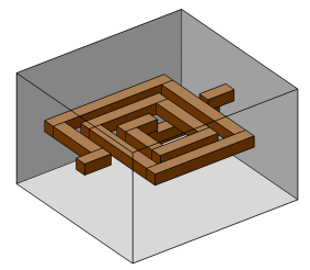
The model geometry consists of the spiral-shaped inductor and the air surrounding it. Figure 1 below shows the inductor and air domains used in the model. The outer dimensions of the model geometry are around 0.3 mm.
Figure 1: Inductor geometry and the surrounding air.
The model equations are the following:
In the equations above, σ denotes the electrical conductivity, A the magnetic vector potential, V the electric scalar potential, Je the externally generated current density vector, μ0 the permittivity in vacuum, and μr the relative permeability.
The electrical conductivity in the coil is set to 106 S/m and 1 S/m in air. The conductivity of air is arbitrarily set to a small value in order to avoid singularities in the model, but the error becomes small as long as the value of the conductivity is small compared with the other conductivities in the model.
The constitutive relation is specified with the expression
where H denotes the magnetic field.
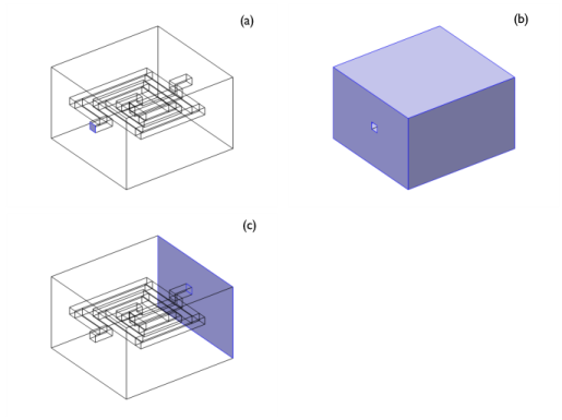
The boundary conditions are of three different types corresponding to the three different boundary groups; see Figure 2 (a), (b), and (c).
Figure 2: Boundaries with the same type of boundary conditions.
The boundary condition for the boundary highlighted in Figure 2 (a) is a magnetic insulation boundary with a terminal boundary condition. For the boundaries in Figure 2 (b), both magnetic and electric insulation prevail. The condition for the last boundary, Figure 2 (c), is magnetic insulation set to a constant electric potential of 0 V (ground).
Results
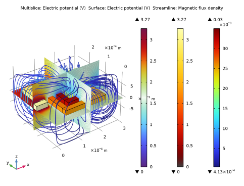
Figure 3 shows the electric potential in the inductor and the magnetic flux lines. The color of the flow lines represents the magnitude of the magnetic flux. As expected this flux is largest in the middle of the inductor.
Figure 3: Electric potential in the device and magnetic flux lines around the device.
The computed self-inductance is 0.75 nH.
Application Library path: ACDC_Module/Inductive_Devices_and_Coils/spiral_inductor
Modeling Instructions
From the File menu, choose New.
New
In the New window, click  Model Wizard.
Model Wizard
1
In the Model Wizard window, click  3D.
2
In the Select Physics tree, select AC/DC>Electromagnetic Fields>Vector Formulations>Magnetic and Electric Fields (mef).
3
Click Add.
4
Click  Study.
5
In the Select Study tree, select General Studies>Stationary.
6
Geometry 1
Import 1 (imp1)
1
In the Home toolbar, click  Import.
2
In the Settings window for Import, locate the Import section.
3
Click  Browse.
4
5
Click  Import.
6
Click the  Wireframe Rendering button in the Graphics toolbar.
This geometry would be relatively straightforward to create from scratch; here it is imported for convenience.
Materials
Conductor
1
In the Model Builder window, under Component 1 (comp1) right-click Materials and choose Blank Material.
2
Right-click Material 1 (mat1) and choose Rename.
3
In the Rename Material dialog box, type Conductor in the New label text field.
4
5
6
In the Settings window for Material, locate the Material Contents section.
7
Air
1
In the Model Builder window, right-click Materials and choose Blank Material.
2
Right-click Material 2 (mat2) and choose Rename.
3
In the Rename Material dialog box, type Air in the New label text field.
4
5
6
In the Settings window for Material, locate the Material Contents section.
7
Setting the conductivity to zero in the air would lead to a numerically singular problem. You can avoid this problem by using a small nonzero value. As 1 S/m is much less than the electric conductivity in the inductor, the fields will only be marginally affected.
Magnetic and Electric Fields (mef)
Magnetic Insulation 1
In the Model Builder window, under Component 1 (comp1)>Magnetic and Electric Fields (mef) click Magnetic Insulation 1.
Terminal 1
1
In the Physics toolbar, click  Attributes and choose Terminal.
2
3
In the Settings window for Terminal, locate the Terminal section.
4
In the I0 text field, type 1.
Magnetic Insulation 1
In the Model Builder window, click Magnetic Insulation 1.
Ground 1
1
In the Physics toolbar, click  Attributes and choose Ground.
2
This concludes the boundary settings. Note that the boundaries that you have not assigned are electrically and magnetically insulated by default.
Mesh 1
1
In the Model Builder window, under Component 1 (comp1) click Mesh 1.
2
In the Settings window for Mesh, locate the Physics-Controlled Mesh section.
3
From the Element size list, choose Coarser.
4
In the Home toolbar, click  Build Mesh.
Study 1
Click  Compute.
Results
Magnetic Flux Density Norm (mef)
The default plot shows the electric potential distribution in three cross-sections. There are plenty of other ways of visualizing the solution. The following instructions detail how to combine an electric potential distribution plot on the surface of the inductor with a streamline plot of the magnetic flux density in the air surrounding it.
3D Plot Group 3
In the Home toolbar, click  Add Plot Group and choose 3D Plot Group.
Surface 1
1
In the Model Builder window, right-click Electric Potential (mef) and choose Surface.
2
In the Settings window for Surface, locate the Coloring and Style section.
3
From the Color table list, choose ThermalDark.
Study 1/Solution 1 (sol1)
In the Model Builder window, expand the Results>Datasets node, then click Study 1/Solution 1 (sol1).
Selection
1
In the Results toolbar, click  Attributes and choose Selection.
Selecting the boundaries of the inductor is most effectively done by first selecting all boundaries, then removing the exterior boundaries of the air box from the selection.
2
In the Settings window for Selection, locate the Geometric Entity Selection section.
3
From the Geometric entity level list, choose Boundary.
4
From the Selection list, choose All boundaries.
5
Streamline 1
1
In the Model Builder window, right-click Electric Potential (mef) and choose Streamline.
2
In the Settings window for Streamline, locate the Streamline Positioning section.
3
From the Positioning list, choose Starting-point controlled.
4
In the Points text field, type 3.
5
Locate the Coloring and Style section. Find the Line style subsection. From the Type list, choose Tube.
6
In the Tube radius expression text field, type 1e-6.
7
Select the Radius scale factor check box.
8
Click to expand the Quality section. From the Resolution list, choose Finer.
9
In the Electric Potential (mef) toolbar, click  Plot.
The Magnetic Insulation condition on the exterior boundaries causes the field lines to bend and follow the contours of the box. This inevitably introduces a systematic error to the inductance computation. It would be possible to reduce this error by increasing the size of the box, or introducing an infinite element domain. Nevertheless, since the field is comparatively small near the surface of the box, the result is reasonably accurate already. Try visualizing the local magnitude of the field by having it decide the color of the streamlines.
Color Expression 1
1
Right-click Streamline 1 and choose Color Expression.
2
In the Settings window for Color Expression, click Replace Expression in the upper-right corner of the Expression section. From the menu, choose Component 1 (comp1)>Magnetic and Electric Fields>Magnetic>mef.normB - Magnetic flux density norm - T.
Streamline 1
1
In the Model Builder window, click Streamline 1.
2
In the Electric Potential (mef) toolbar, click  Plot.
Global Evaluation 1
1
In the Results toolbar, click  Global Evaluation.
2
In the Settings window for Global Evaluation, click Replace Expression in the upper-right corner of the Expressions section. From the menu, choose Component 1 (comp1)>Magnetic and Electric Fields>Terminals>mef.L11 - Inductance - H.
3
Click  Evaluate.
Table
1
Go to the Table window.
The inductance evaluates to 0.75 nH.