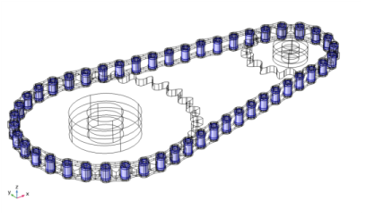
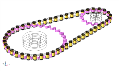
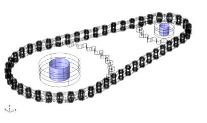
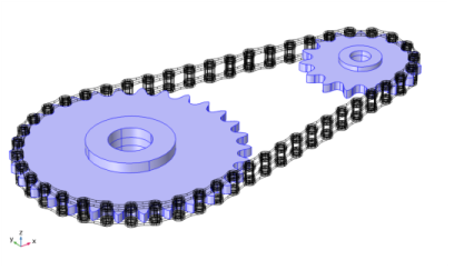
Using the Chain Drive node in the Multibody Dynamics interface, you can model a roller chain sprocket assembly in 2D or 3D. The Chain Drive node determines the interaction of the chain drive assembly, and automatically generates a set of physics nodes that are used to describe its behavior.
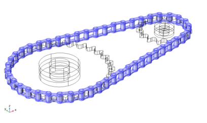
This is a domain selection input used to create a Rigid Domain node on each link plate of the chain. If you use a geometry from the COMSOL Part Library, a built-in domain selection named Links is automatically selected. If you are using your own geometry, you need to input a domain selection containing all link plates. This selection input is available only when the chain links are modeled as rigid bodies.
This is a domain selection input used to create a Rigid Domain node on each sprocket. If you use a geometry from the COMSOL Part Library, a built-in domain selection named Sprockets is automatically selected. If you are using your own geometry, you need to input a domain selection containing both sprockets domains. This selection input is available only when the sprockets are modeled as rigid bodies.
For 2D models created from the COMSOL Part Library, a selection named Pin Inner Boundaries is automatically selected. If you use your own geometry, you need to input a boundary selection containing the inner boundaries of all pin plates.
Using Chain Drive node, you can either model the chain links as rigid or elastic bodies. If the link plates are assumed rigid, the
Chain Drive node automatically creates a
Rigid Domain node for each link plate, see
Domain Selection, Link. It is also possible to model a chain with elastic bushings present between rigid link plates, see
Domain Selection, Bushing.
For the mesh-based contact method, the Chain Drive node automatically creates a contact pair between the outer boundaries of the rollers and the outer boundaries of the sprockets. A
Contact node with penalty formulation is also added to the physics, which uses the created Contact Pair for computing the contact forces.
The Chain Drive node automatically generates a
Hinge Joint node between each roller and pin plate. The axis of the
Hinge Joints is the same as the sprocket axis. If you use a geometry form the COMSOL Part Library, the sprocket axis is automatically taken from the geometry part. It is also possible to change the axis of the sprocket, either by specifying a direction, or by selecting an edge parallel to the sprocket axis.
The Attachment nodes created on the roller and pin plates having same geometrical positions are used as the source and destination for the corresponding
Hinge Joint. These attachments can either be rigid or flexible, depending on the setting in the parent
Chain Drive node.
By default, the joints are assumed rigid, and the source and destination attachments are then rigidly connected in the directions in which the relative motion is restricted. However, it is possible to insert an elastic connection between attachment surfaces by setting Joint Type to
Elastic in the
Chain Drive node. This automatically sets all
Hinge Joint nodes to be elastic. From the
Chain Drive node, you can also control the viscous damping properties of each
Hinge Joint in order to model losses, by activating rotational damping and setting a value for the damping coefficient
c.
The Creates Link and Joints Button is used to generate all physics nodes required to model the roller chain sprocket assembly. Keep the following points in mind when using this button:


