Use a Rotated System (

) to define an orthonormal coordinate system which is rotated with respect to the reference system. In 2D, you can specify either an in-plane rotation angle or a full 3D rotation using Euler angles. In 3D, Euler angles (Z-X-Z) is the only option.
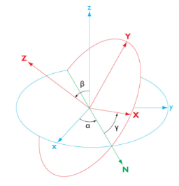
Full 3D rotations are specified as three consecutive Euler angles α,
β, and
γ, using a
Z-X-Z convention. Rotation axes and angles are illustrated in
Figure 5-4 where the resulting rotated system axes are denoted
X,
Y, and
Z.
The transformation matrix defined by the Euler angles transforms components of a fixed vector v from the rotated coordinate system,
[vX,vY,vZ], to components in the global system,
[vx,vy,vz], as follows:
If this coordinate system is added as a subnode to a Combined System node, define where it will be active using a selection in the
Geometric Entity Selection section. Also, the
Name and
Coordinate names fields are not available in this case.
In the Coordinate names table, the default names are entered —
x1,
x2, and
x3. In planar 2D models,
x1 and
x2 are typically the in-plane coordinates, and
x3 is the out-of-plane coordinate.
When the input method is set to In-plane rotation in a 2D component, you specify the rotation as a single angle (in radians) representing the
Rotation about out-of-plane axis. The
Out-of-plane axis can be set to any of the three main axes, pointing either into or out of the screen. The default for planar 2D geometries is
Third out-of screen, which leaves the
x and
y axes as in-plane reference axes. For axisymmetric geometries, the default is
Second out-of screen, leaving the
r and
z axes in-plane.
For 3D geometries and when General rotation has been chosen as input method in 2D, enter the
Euler angles (Z-X-Z) (in radians) in the
α,
β, and
γ fields (see the graphics in the
Settings window for definitions of these angles). The default values are 0 for all angles.
Specify the location of the Origin of the base vector coordinate system in the global Cartesian system. The default is an origin coinciding with the one from the global system using the frame chosen from the
Frame list (default:
Spatial).
From the Work plane list, select
xy-plane (the default, for a standard global Cartesian coordinate system) or select any work plane in the geometry sequence. If you choose a work plane, the work plane’s coordinates
xw,
yw, and
zw are used for the definition of the rotated system.
