You are viewing the documentation for an older COMSOL version. The latest version is
available here
.
Visualizing 3D Geometry and Fiber Draping
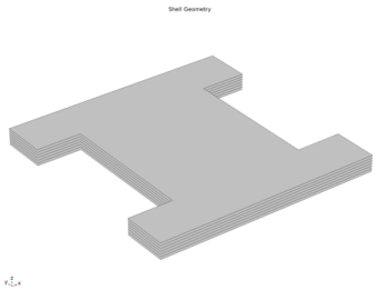
In complex structures, sometimes it becomes important to visualize the 3D solid geometry which corresponds to a composite laminate modeled using the surface geometry. It gives a clear picture of the number of layers as well as laminate thickness in different regions of the structure. In order to visualize this, a default plot is added in the Layered Shell and Shell interfaces as shown in
Figure 3-15
.
Figure 3-15:
3D solid geometric representation (scaled in thickness direction) of a composite laminate having six layers.
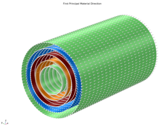
In addition to visualizing the stacking sequence of a laminate, visualization of the fiber draping direction on the physical geometry is also useful. A default plot is added in the Layered Shell and Shell interfaces as shown in
Figure 3-16
.
Figure 3-16:
First principal material direction showing the fiber draping direction in each layer of a composite cylinder.