The dependent variables in 3D are the displacements u,
v, and
w in the global
x,
y, and
z directions, and the displacements of the shell normals
ax,
ay, and
az in the global
x,
y, and
z directions.
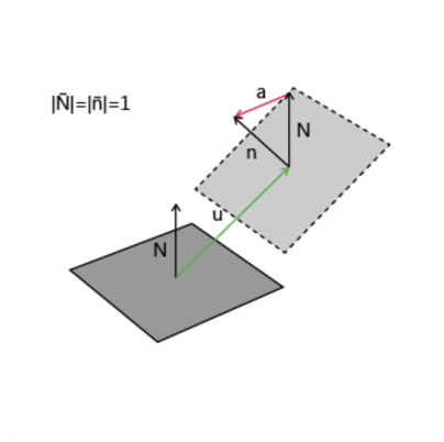
where uR is the displacement on the reference surface (the displacement degrees of freedom) and
ζ0 is the offset. The rotational displacement
a is the same on both midsurface and reference surface.
For input and output, the Shell interface to a large extent replaces the displacements of the shell normals by the more customary rotations θx,
θy, and
θz about the global axes. For a geometrically linear analysis, the relation between normal displacement and rotation vector is simple:
a = θ × n where
n is the unit normal of the shell.
For a standard plate analysis only three degrees of freedom are needed: the out-of-plane displacement w and the displacements of the shell normals
ax and
ay. It is also possible to activate all six degrees of freedom, so that any type of analysis of a shell initially positioned in the
xy-plane can be performed using the Plate interface. Using six degrees of freedom is the default, but three degrees of freedom can be selected instead for efficiency.
For plates, the rotations θx,
θy, and (possibly)
θz are used to a large extent.