Solid Mechanics
The Solid Mechanics interface offers the most general modeling of structural mechanics problems and is formulated based on general principles of continuum mechanics. It is the interface which contains the largest number of material models, and the most advanced boundary conditions. It is also the only physics interface that supports contact analysis.
The drawback with using solid elements is that the models can become computationally expensive, especially in 3D. For structures which are thin or slender, you should consider using one of the specialized physics interfaces.
3D Solid Geometry
The degrees of freedom (dependent variables) in 3D are the global displacements u, v, and w in the global x, y, and z directions, respectively.
Figure 2-1: Loads and constraints applied to a 3D solid using the Solid Mechanics interface.
2D Geometry
Plane Stress
The plane stress variant of the 2D physics interface is useful for analyzing thin in-plane loaded plates. For a state of plane stress, the out-of-plane components of the stress tensor are zero.
Figure 2-2: Plane stress is used to model plates where the loads are only in the plane; it does not include any out-of-plane stress components.
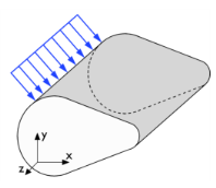
The 2D physics interface for plane stress allows loads in the x and y directions, and it assumes that these are constant throughout the material’s thickness, which can vary with x and y. The plane stress condition prevails in a thin flat plate in the xy-plane loaded only in its own plane and without any z direction restraint.
Plane Strain
The plane strain variant of the 2D physics interface that assumes that all out-of-plane strain components of the total strain εz, εyz, and εxz are zero.
Figure 2-3: A geometry suitable for plane strain analysis.
Loads in the x and y directions are allowed. The loads are assumed to be constant throughout the thickness of the material, but the thickness can vary with x and 
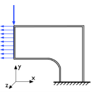
y. The plane strain condition prevails in geometries, whose extent is large in the z direction compared to in the x and y directions, or when the z displacement is in some way restricted. One example is a long tunnel along the z-axis where it is sufficient to study a unit-depth slice in the xy-plane.
Axisymmetric Geometry
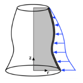
The axisymmetric variant of the Solid Mechanics interface uses cylindrical coordinates r,  (phi), and z. Loads are independent of , and the axisymmetric variant of the physics interface allows loads only in the r and z directions.
The 2D axisymmetric geometry is viewed as the intersection between the original axially symmetric 3D solid and the half plane ϕ = 0,  0. Therefore, the geometry is drawn only in the half plane r 0 and recover the original 3D solid by rotating the 2D geometry about the z-axis.
Figure 2-4: Rotating a 2D geometry to recover a 3D solid.